Page 14 of 30
Re: 1/32 Hasegawa Fw 190D-13 Yellow 10
Posted: Sun Feb 14, 2021 7:11 am
by Thomas_M
Stikpusher wrote:Just enjoying watching your meticulous work!


Such a joy to see you doing your art, John! Better than modelling myself!
Re: 1/32 Hasegawa Fw 190D-13 Yellow 10
Posted: Sun Feb 14, 2021 7:02 pm
by jkim
Re: 1/32 Hasegawa Fw 190D-13 Yellow 10
Posted: Mon Feb 15, 2021 1:21 am
by jkim
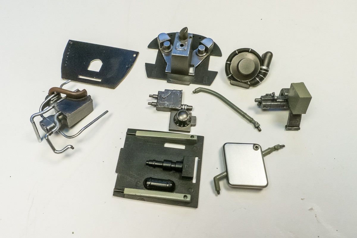
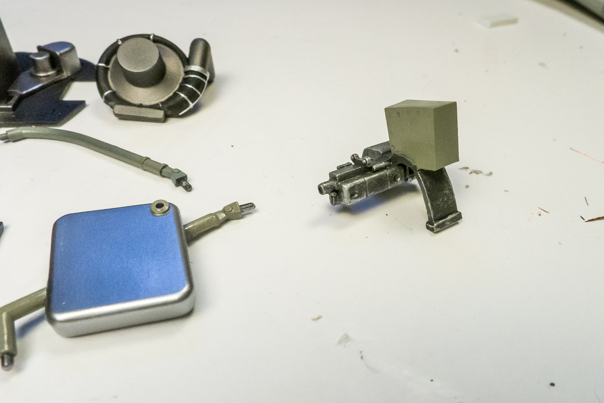
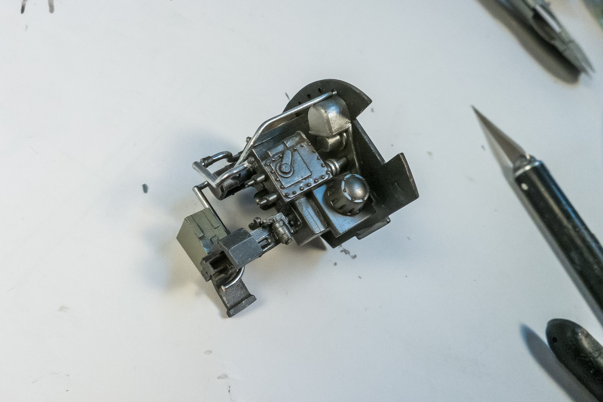
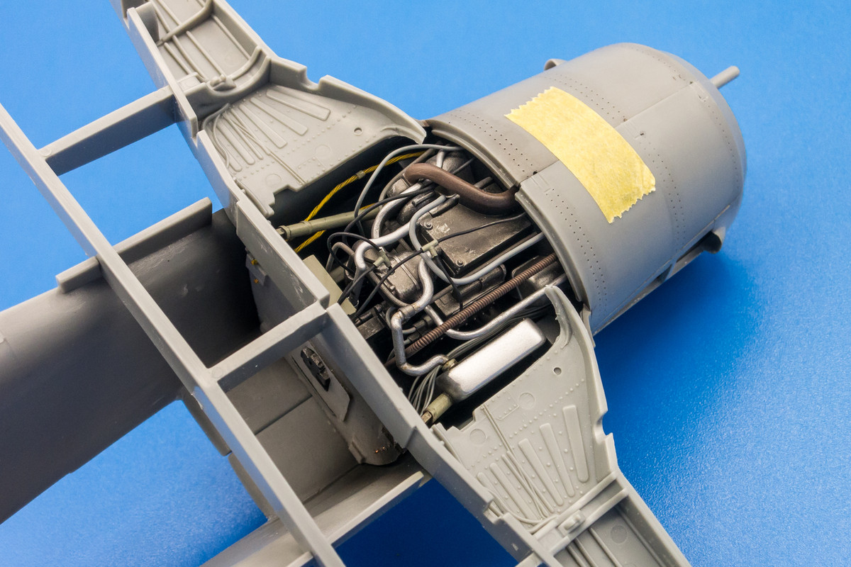
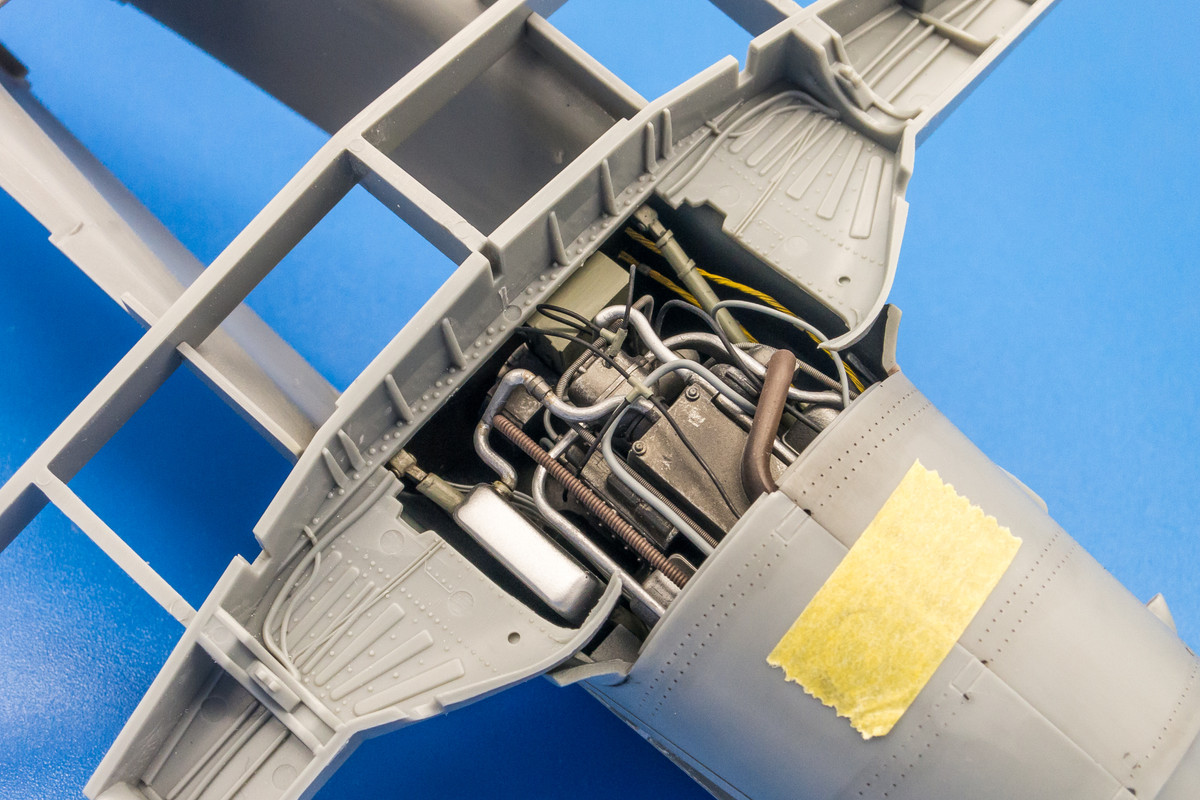
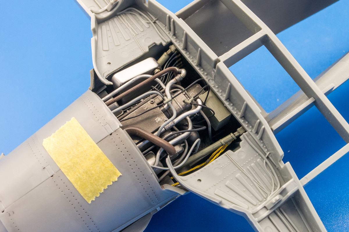
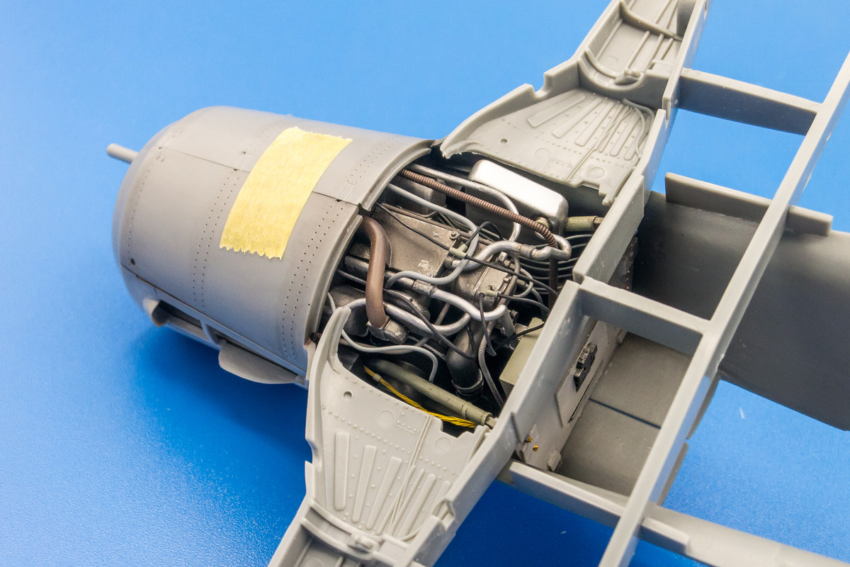
Work on the engine continues. Since real photos of this area are limited, I am using lots of artistic license to fill this empty space with appropriate, if not accurate, complexity. I just want it to look passably busy. On one hand, it's pretty easy work since the engine space is represented by a small finite box with bulkheads on either side to pass wires between. But since most of it is fictional, it's difficult to visualize what I should do. Just gotta dive in...
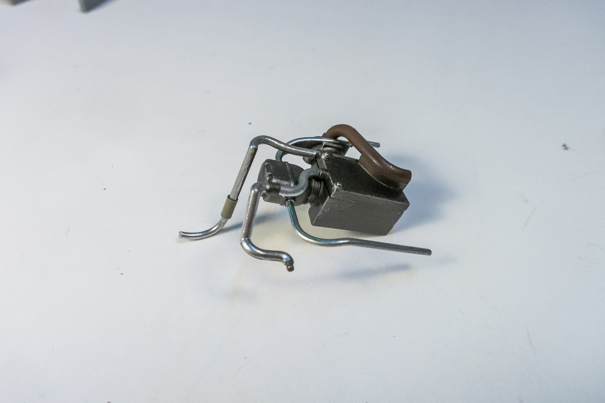
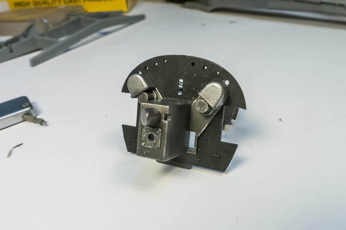
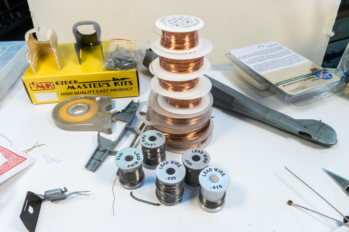
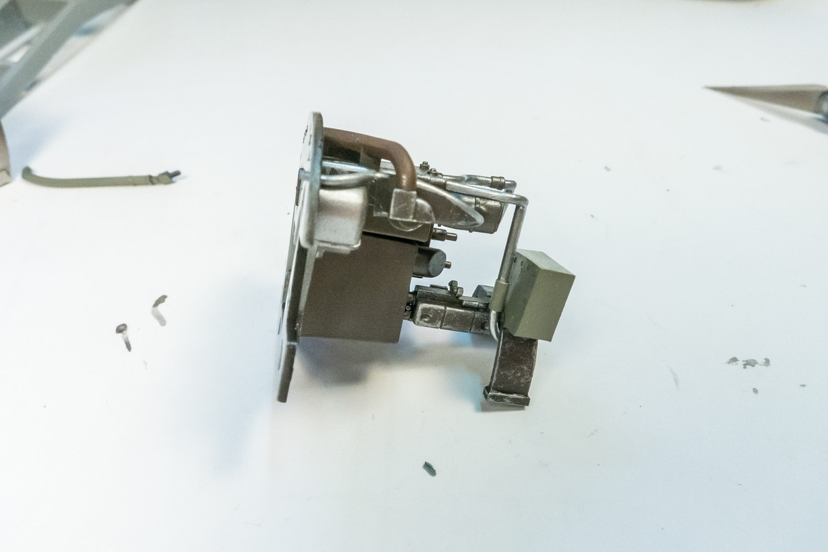
Random holes have been drilled into the front and rear bulkheads to accept the wiring. I am using either copper or lead wire in various gauges as well as some metal guitar string, to mimic the mass of hydraulic lines found at the rear of the Jumo 213 engine. The wiring is added as the "box" of the engine compartment is put together.
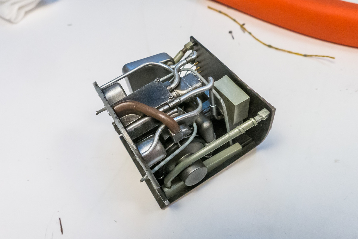
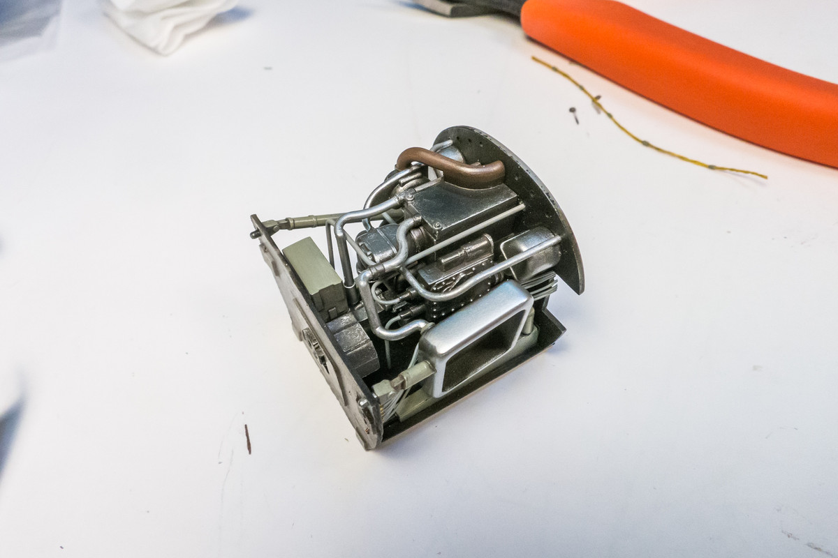
At intermediate stages, I place the engine assembly within the fuselage to check my progress.
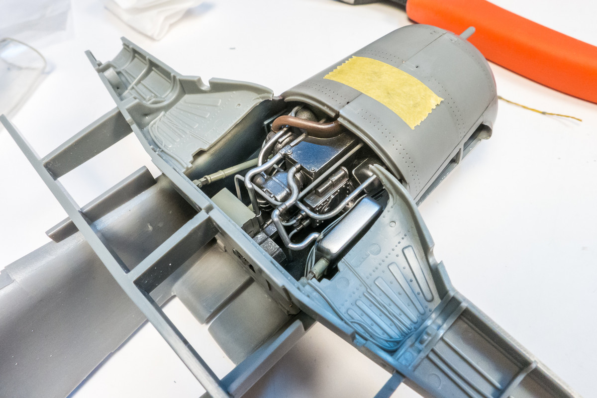
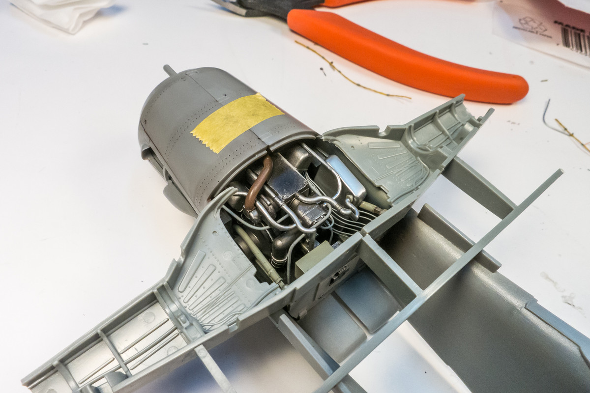
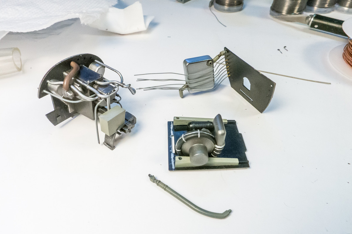
After a few hours, the engine box is complete.
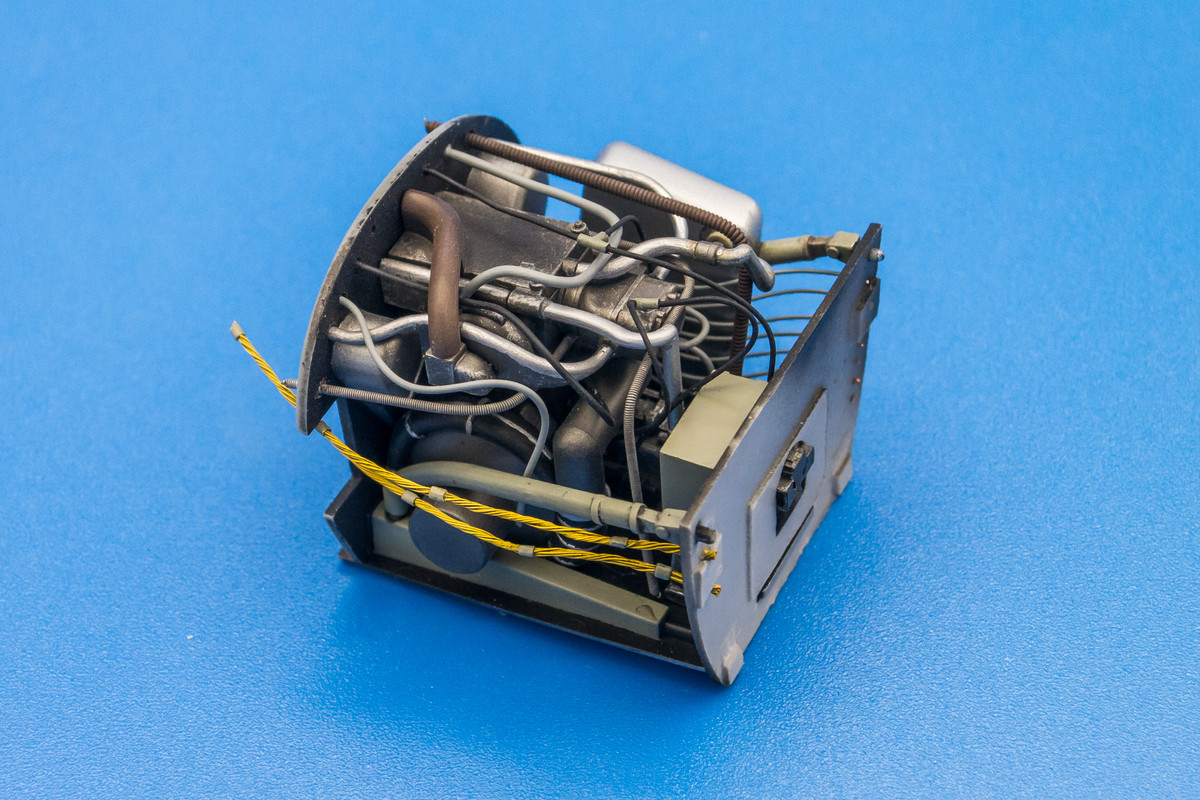
The complete engine box is posed with the kit wheel well. If you recall, I also have the Aires resin wheel well set, which I was planning to use but now I could go either way. The final view into the kit wheel well will be restricted by the wing bottom but this lets us enjoy the completion of this step in the context of its placement within the fuselage.
Re: 1/32 Hasegawa Fw 190D-13 Yellow 10
Posted: Mon Feb 15, 2021 2:30 am
by Stuart
That's a bloody impressive bit of engine work and detailing John - that'll look aces when the rest of the model is finished around it.
Re: 1/32 Hasegawa Fw 190D-13 Yellow 10
Posted: Mon Feb 15, 2021 4:47 am
by tempestjohnny
Unbelievable
Re: 1/32 Hasegawa Fw 190D-13 Yellow 10
Posted: Mon Feb 15, 2021 10:02 am
by Floki
That's some fine work John. Thank you for sharing your process on this.
Re: 1/32 Hasegawa Fw 190D-13 Yellow 10
Posted: Mon Feb 15, 2021 10:06 am
by Paul
That is some seriously busy modeling, John. Killer.
Re: 1/32 Hasegawa Fw 190D-13 Yellow 10
Posted: Tue Feb 16, 2021 4:58 pm
by jkim
Thanks guys! This is the fourth 1/32 Dora kit and so the fourth engine compartment I've done. And they've all looked different! For this iteration, I added some finer wiring runs up top (actually bottom since we're looking at it upside down) as a nod to the restoration photos of Yellow 10 in my Dora book.
Re: 1/32 Hasegawa Fw 190D-13 Yellow 10
Posted: Tue Feb 16, 2021 6:43 pm
by Stikpusher
VERY impressive plumbing job on there John!
Masterfully done!

Re: 1/32 Hasegawa Fw 190D-13 Yellow 10
Posted: Tue Feb 16, 2021 11:09 pm
by jkim
Thanks Carlos! I have had plenty of practice doing this exact thing!
I decided to glue on the resin supercharger intake. I used JB Kwik Weld since the thick consistency helps hold the part in place. It looks good from this perspective but due to the subtle curvature of the fuselage surface, the supercharger base does not lie flat.
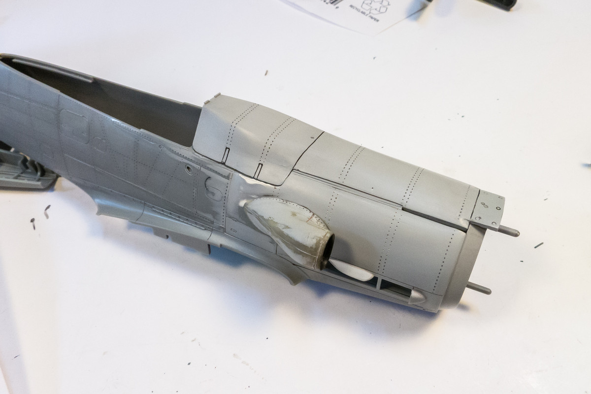
So I had to use some Milliput to fill the gaps and then Mr Surfacer 1000 to blend everything together.
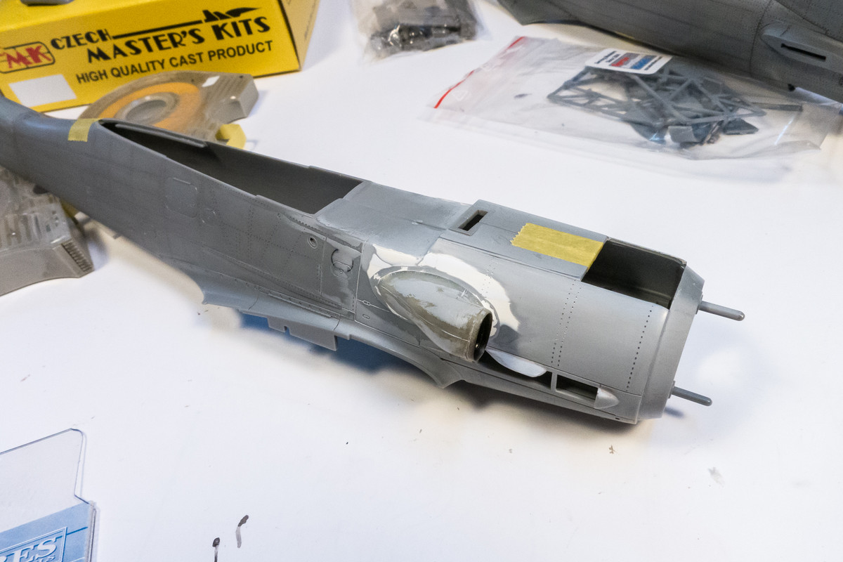
A shot of Mr Primer Surfacer 1000 shows the blend work. Almost too smooth?
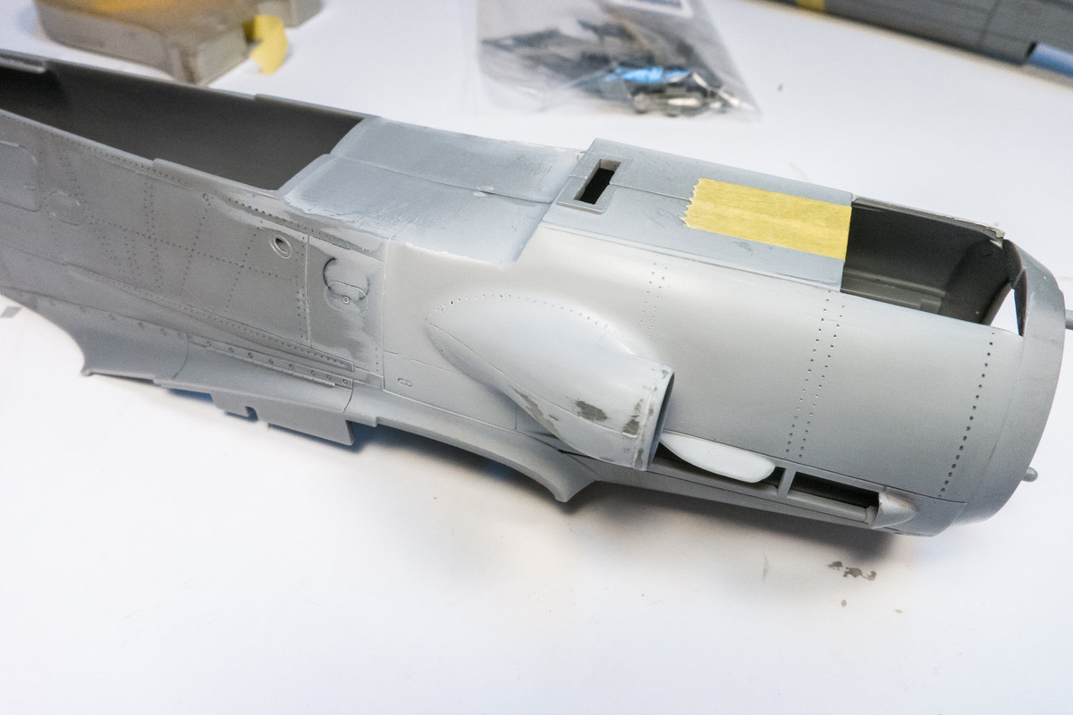
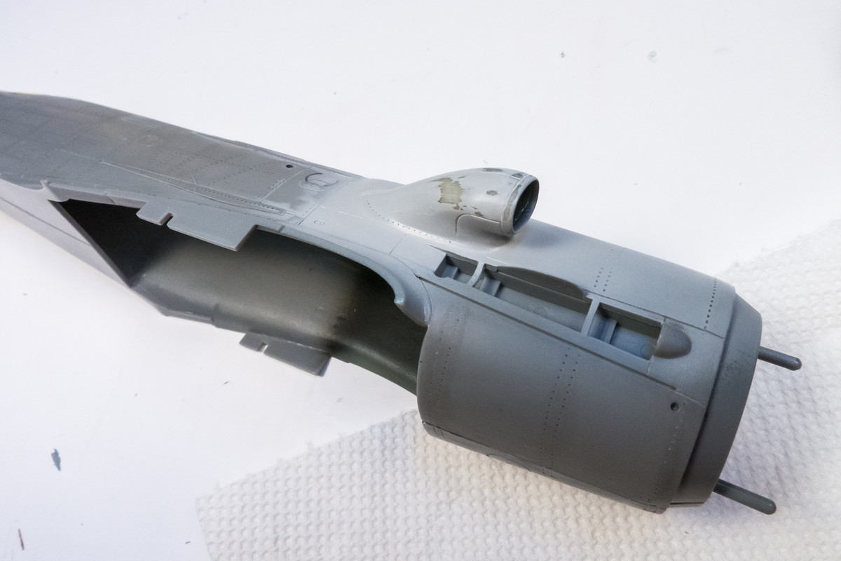
Ideally, there should probably be a seam line running around the base of the intake. But I am afraid of trying to scribe such an irregular shape without it looking shaky. Especially at the front end where I may not be able to fit a scriber. I'll sit on this for a while and ponder what to do next!