Tamiya 1/32 Spitfire XIVe Conversion

Post your work in progress of your aircraft builds in here.
User avatar
jkim
Elite Member
Posts: 4073
Joined: Mon Apr 10, 2017 4:03 pm

Re: Tamiya 1/32 Spitfire XIVe Conversion

Post by jkim »

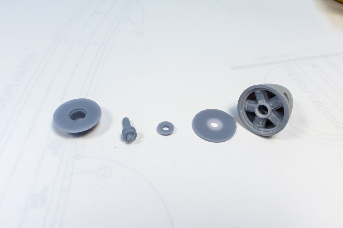
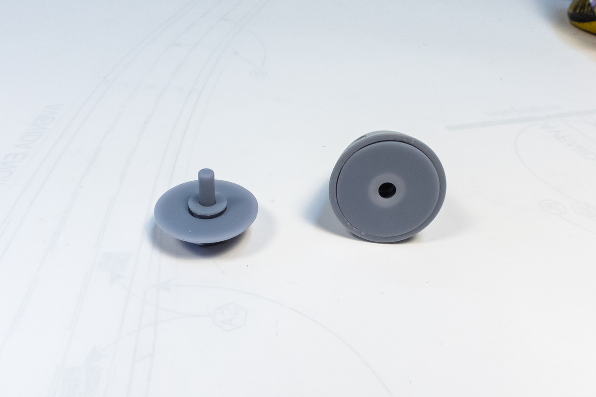
The Amazon delivery arrived on schedule today so here is the spinner trick that I was talking about. LFD provides a well-designed attachment that ensures a centered spinner and is removable and posable. It relies on a kit-supplied polycap that resides in the spinner to hold everything together.
Image
Image
Image

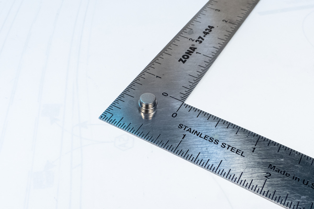
I would've been totally happy with this set up but my sole polycap is securely glued into the Version 1 spinner and my mind started thinking about an alternative. I then remembered a post by Mathieu on Facebook describing the use of small magnets as an alternative way to attach the spinner. I've done similar things on past builds so it was just a matter of ordering the right sized magnents for the job. In this case, you need a 5mm(dia) x2mm(thick) and a 6mmx2mm magnet.
Image

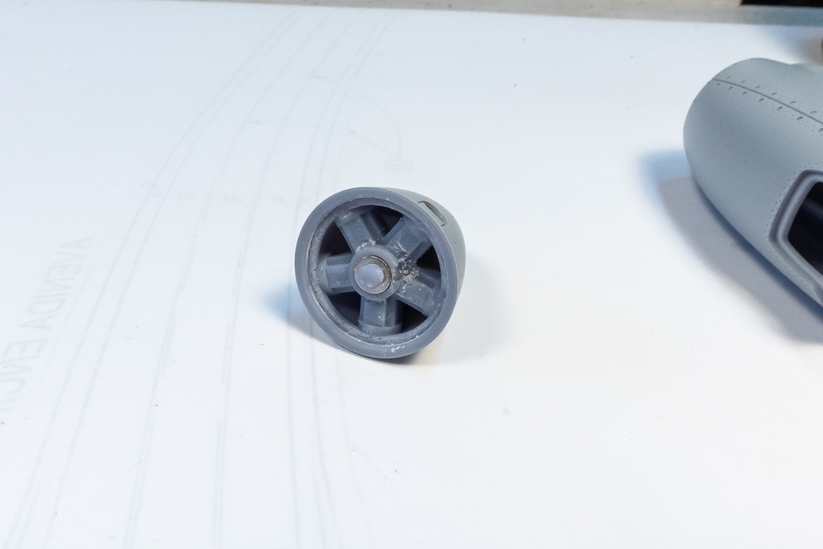
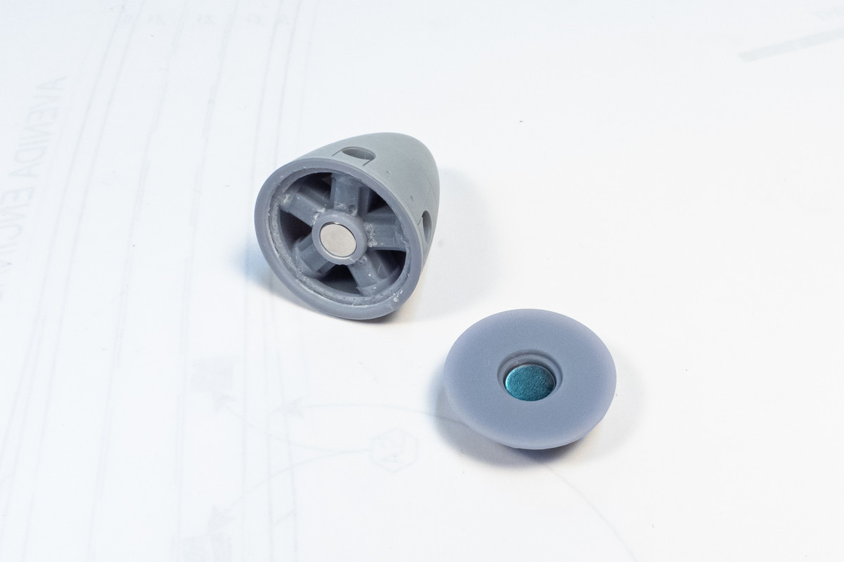
The 5mm magnet goes into the spinner and the 6mm magnet goes into the backing plate that plugs into the front of the fuselage. The hole in the spinner was a little smaller than 5mm so I had to carefully increase its size using a drill bit.
Image

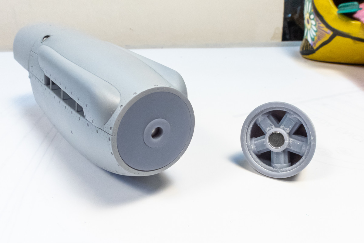
This is all you need to do for the attachment to work.
Image

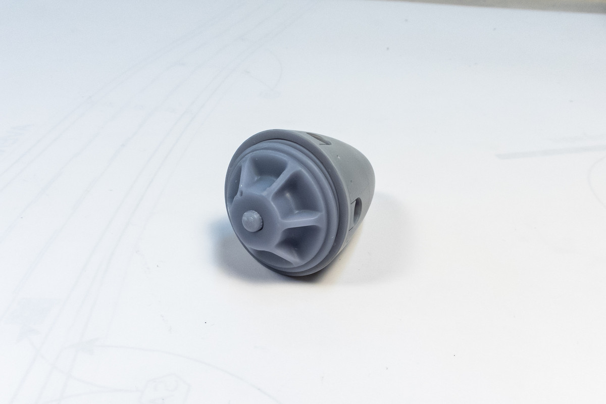
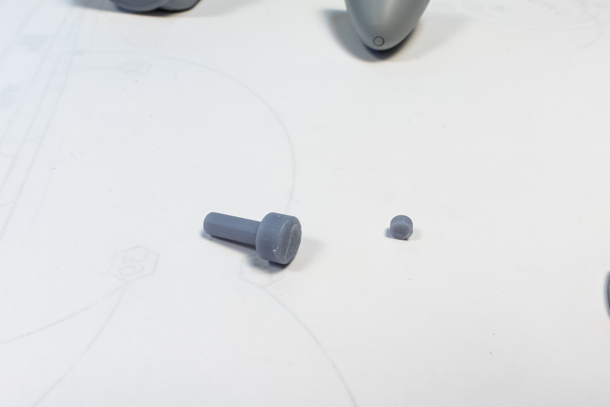
To help center the spinner, I cut a small section from the LFD-supplied prop axle and glued it onto the center of the magnet in the spinner.
Image
Image

Now the spinner snaps into place with that awesome "click" that only a magnetic connection can provide. I'm pretty confident that the weight of the prop blades won't be an issue but I'll document the full prop on the magnetic connection next time.
Image
Image
John aka JKim
-----------<><
Image
User avatar
BlackSheep214
Elite Member
Posts: 13412
Joined: Sun Apr 06, 2014 8:47 pm

Re: Tamiya 1/32 Spitfire XIVe Conversion

Post by BlackSheep214 »

Cool!
“Who controls the skies, controls the fate of this Earth”

Author unknown- 352nd Fighter Group, Blue-Nosed Bastards of Bodney

“Send one plane it’s a sortie; send two planes it’s a flight; send four planes it’s a test of airpower. - Richard Kohn
User avatar
jkim
Elite Member
Posts: 4073
Joined: Mon Apr 10, 2017 4:03 pm

Re: Tamiya 1/32 Spitfire XIVe Conversion

Post by jkim »

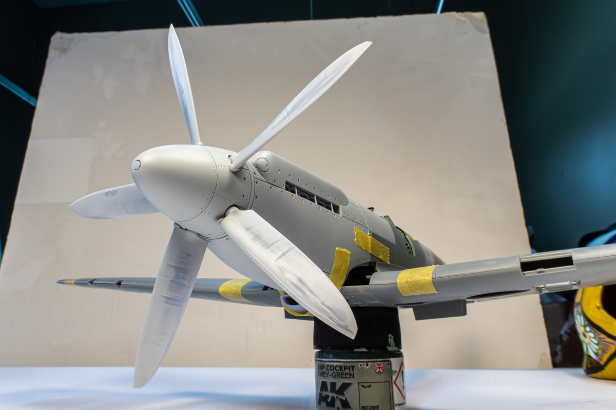
Full prop with five blades... no problem with the magnetic mount.
Image
John aka JKim
-----------<><
Image
User avatar
tempestjohnny
Elite Member
Posts: 3804
Joined: Sat Oct 15, 2016 4:51 am
Location: Naples. FL

Re: Tamiya 1/32 Spitfire XIVe Conversion

Post by tempestjohnny »

Great idea on the prop
User avatar
Gary Brantley
Elite Member
Posts: 2738
Joined: Tue Apr 08, 2014 9:40 pm
Location: Cameron, Texas

Re: Tamiya 1/32 Spitfire XIVe Conversion

Post by Gary Brantley »

tempestjohnny wrote: Sun Jun 09, 2024 3:11 am Great idea on the prop
Yes, it is!! :shoutout:
User avatar
jkim
Elite Member
Posts: 4073
Joined: Mon Apr 10, 2017 4:03 pm

Re: Tamiya 1/32 Spitfire XIVe Conversion

Post by jkim »

Thanks guys!

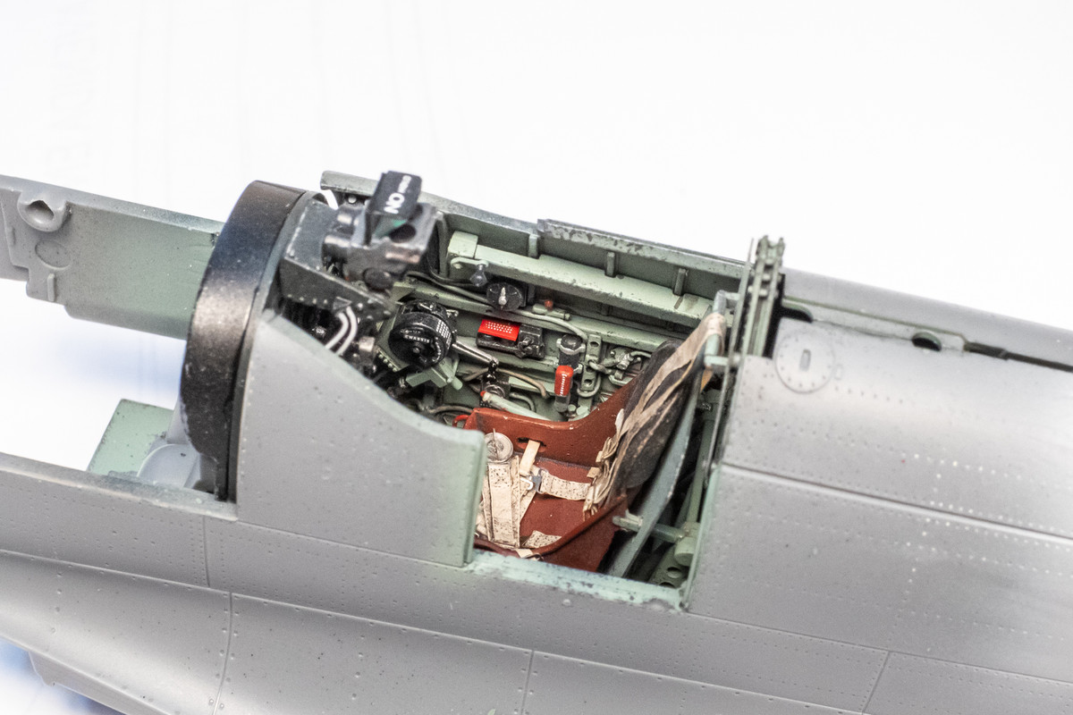
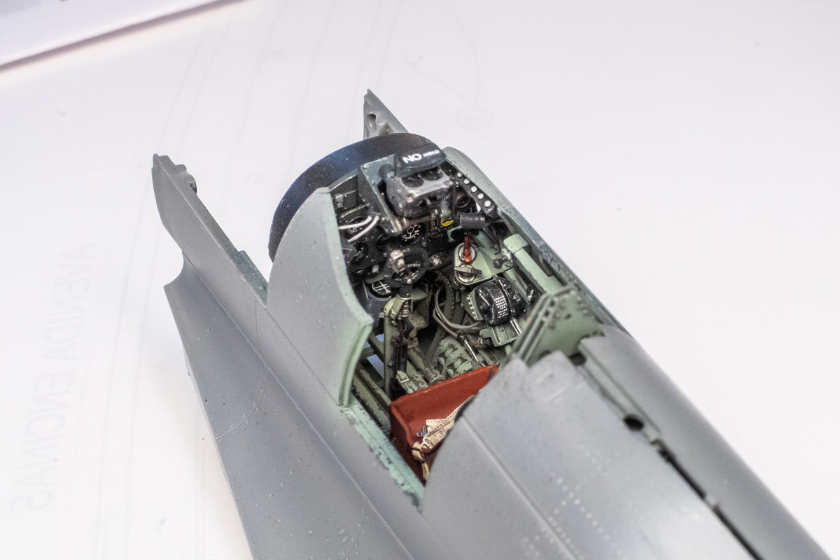
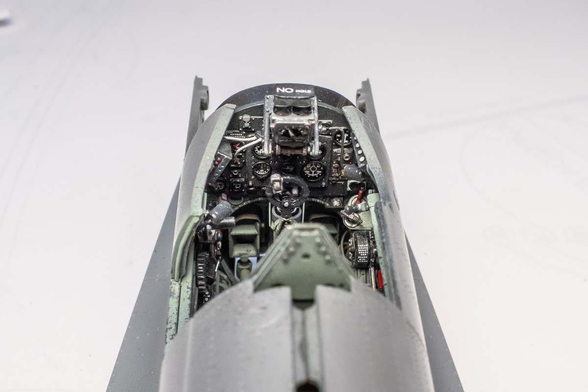
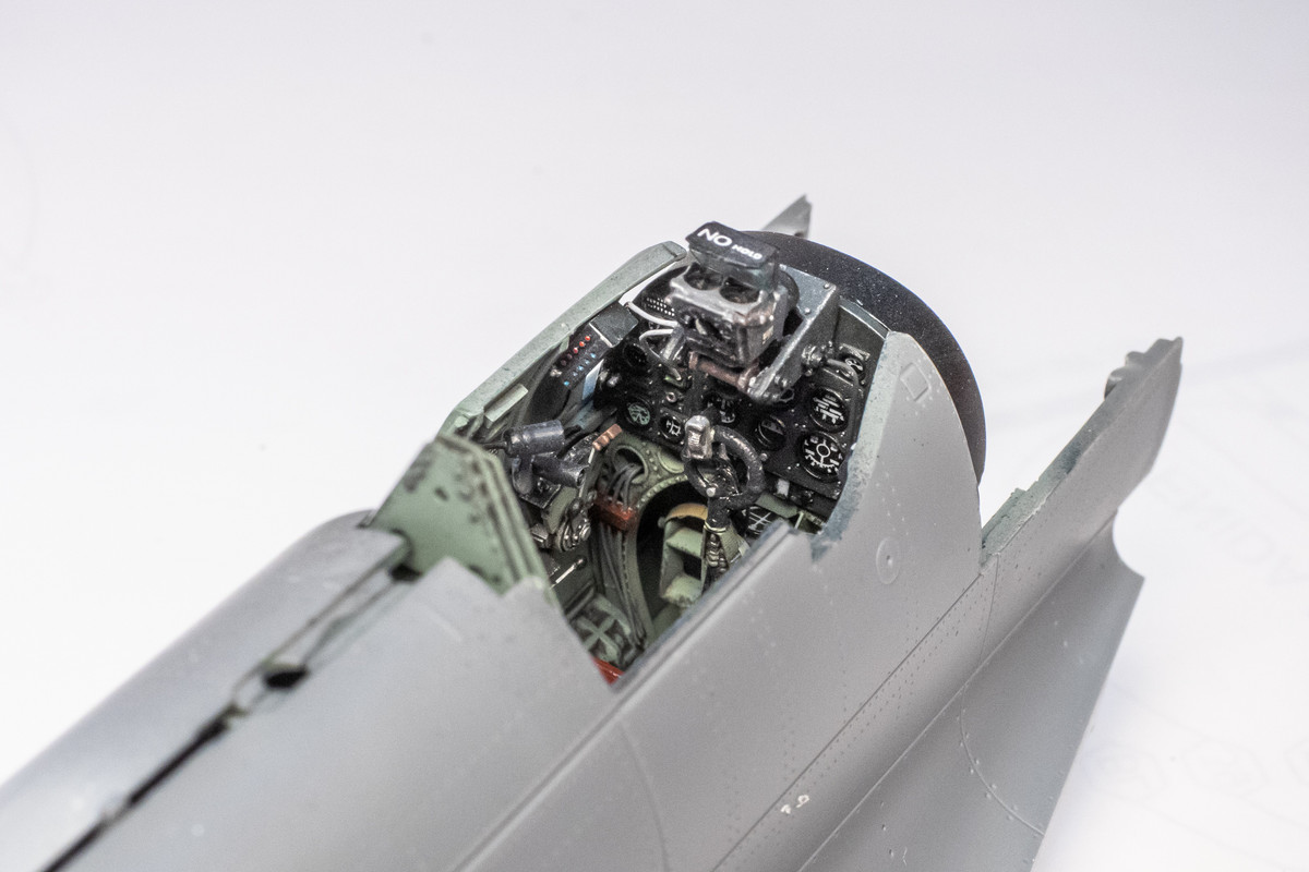
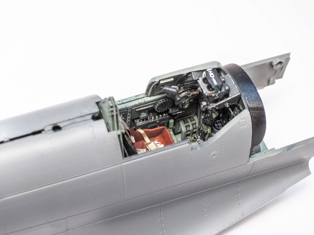
With the pilot door situation addressed, I've glued the fuselage halves together, finally. I've added a couple of wires on the port side of the gunsight that lead to the throttle. The view into the cockpit will only get more and more limited as we move forward so I'm getting as many cockpit shots as I can.
Image
Image
Image
Image
Image

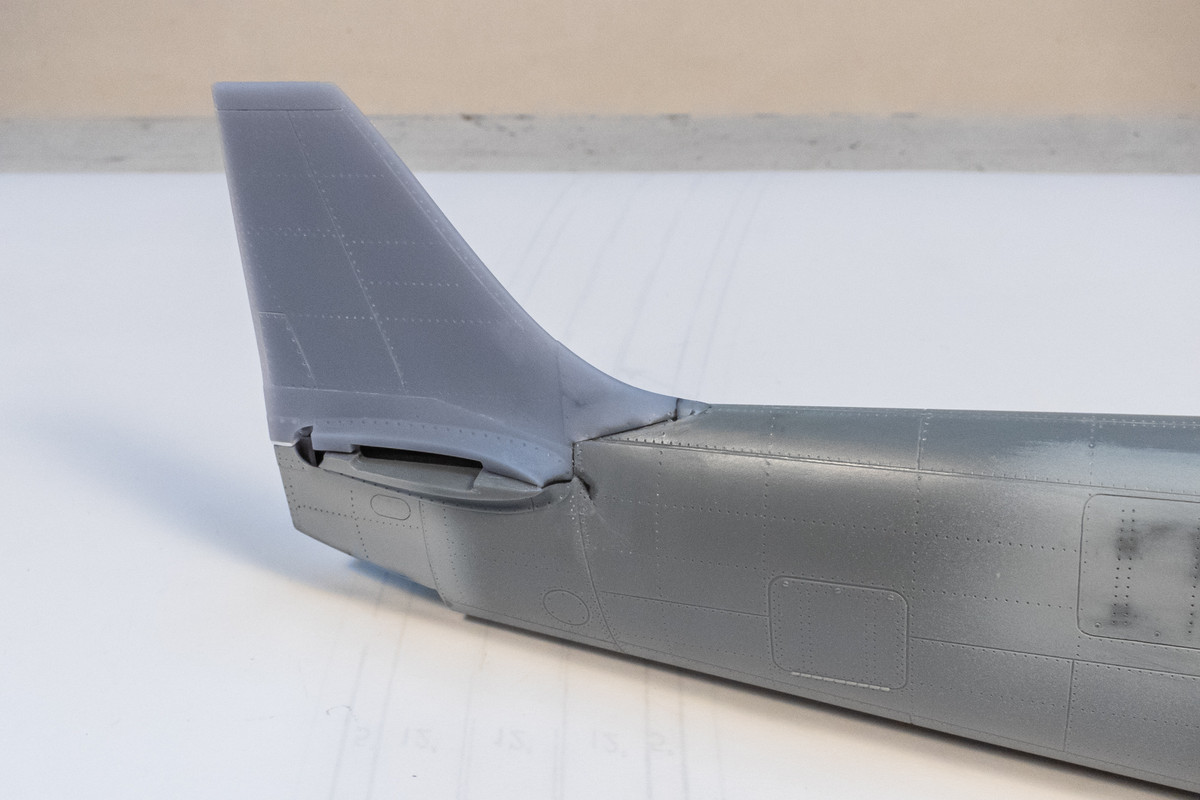
The LFD tail is now glued into place. It didn't go as well I had hoped, breaking off the tip of the spine where it meets the fuselage and even cracking the kit fuselage at the base of the horizontal stabilizers.
Image

With two versions of the tail, I had the necessary spares to cut a piece from an unused tail part for the repair. Black CA glue was used for the majority of this repair. It was applied to all of the joints. But instead of sanding right away, I used a cotton bud dipped in CA debonder and wiped away all of the excess and leaving only a thin bead of glue within the joints themselves. This works well for gaps in joints along a panel line with little or no sanding needed. In places where I needed to feather the filler flush (like the crack at the base of the stabilizers), I used the standard approach: sandpaper.
Image

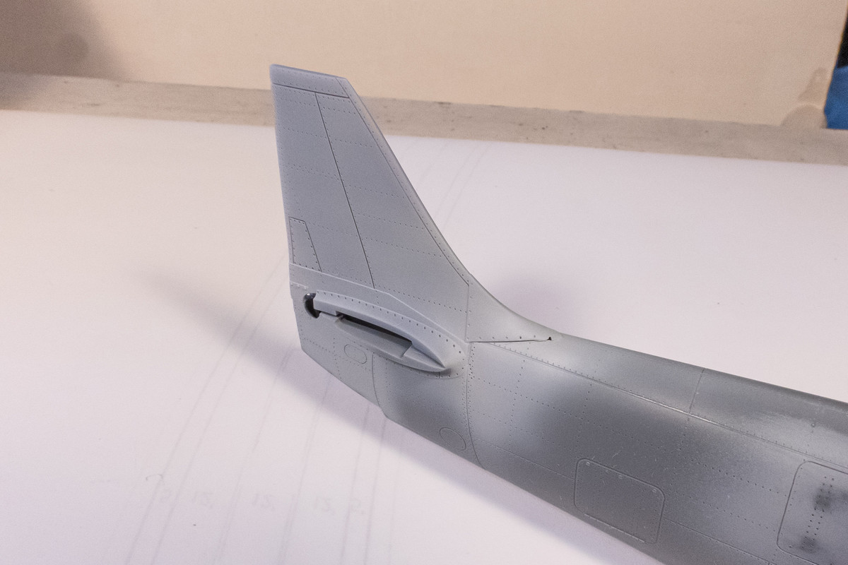
After the first round of repair, the tail joints are sprayed with primer to check the work. Crack is addressed but more work is needed on the spine.
Image

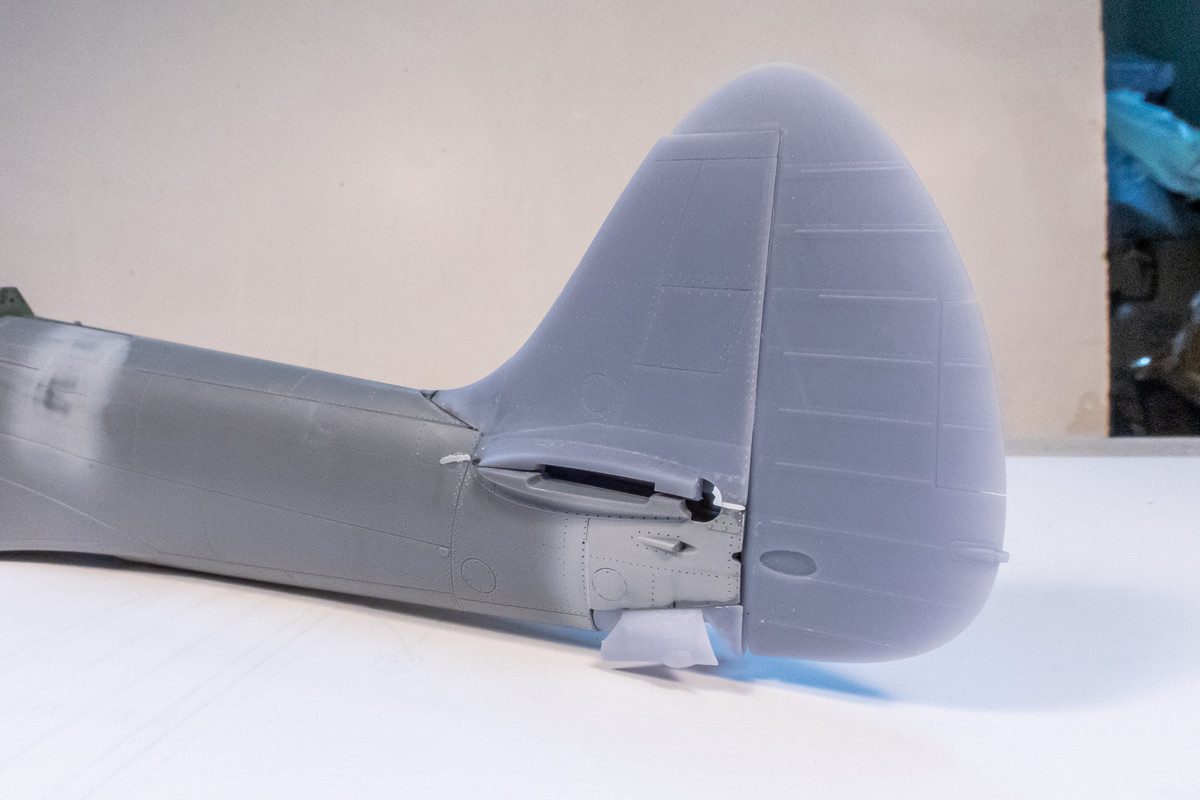
The rudder can now be test fitted along with the tail wheel well.
Image

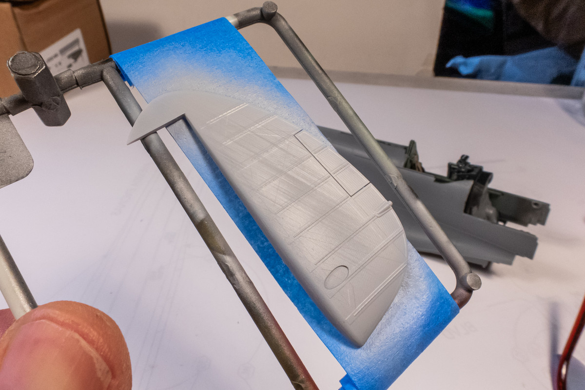
The 3D parts from LFD can vary in quality. Mostly excellent. But some parts have more prominent ridges on their surface than others. The rudder is one of those parts and you can still make out the ridges after a coat of primer. I could've used the previous version of this same rudder which was much cleaner but unfortunately, the counter-balance top is broken off and unaccounted for. Which is another great reminder... these 3D parts are very delicate and can be prone to breakage if you are not careful. I am learning the hard way!
Image

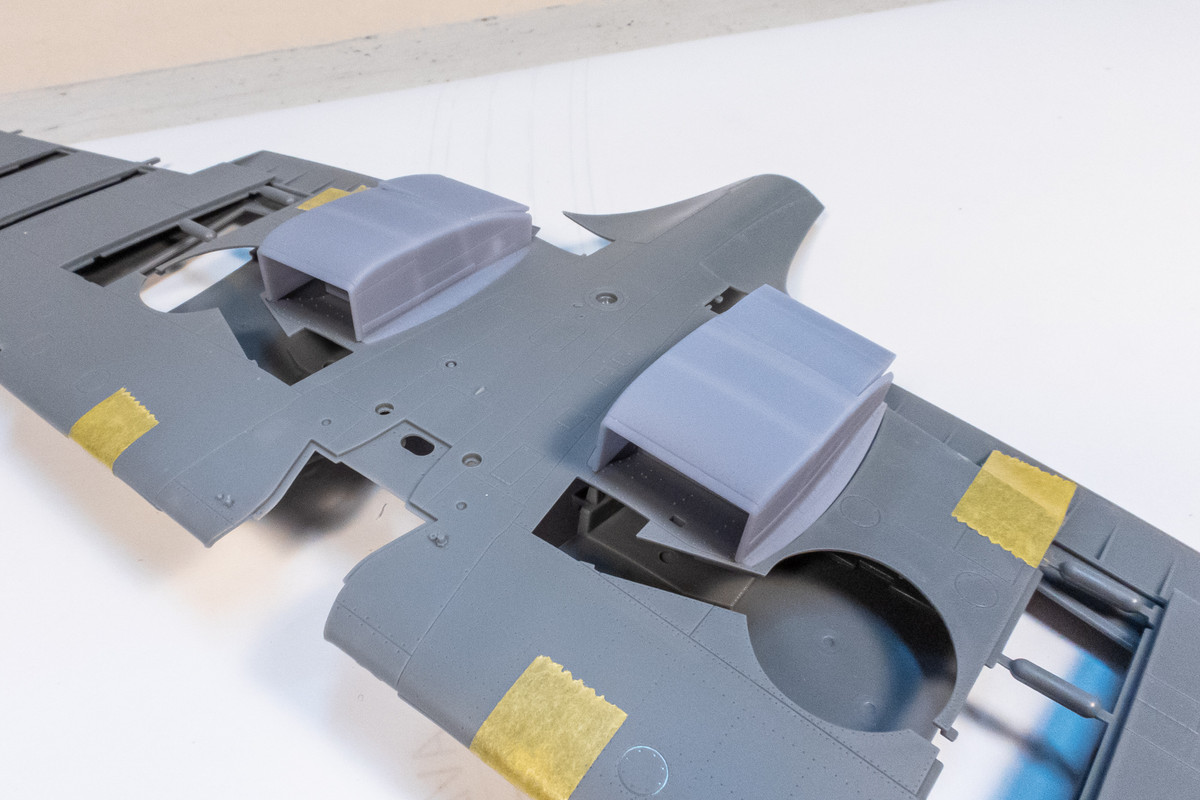
A test fit of the under-wing radiator boxes. The grate faces within the boxes are separate parts and I found that they were about 0.5mm too wide. Fit is much better after trimming down all four of these down.
Image
John aka JKim
-----------<><
Image
User avatar
BlackSheep214
Elite Member
Posts: 13412
Joined: Sun Apr 06, 2014 8:47 pm

Re: Tamiya 1/32 Spitfire XIVe Conversion

Post by BlackSheep214 »

Nice work! The cockpit is incredible! Lifelike enough to want to sit in it. :lashed: :giggles:
“Who controls the skies, controls the fate of this Earth”

Author unknown- 352nd Fighter Group, Blue-Nosed Bastards of Bodney

“Send one plane it’s a sortie; send two planes it’s a flight; send four planes it’s a test of airpower. - Richard Kohn
User avatar
tempestjohnny
Elite Member
Posts: 3804
Joined: Sat Oct 15, 2016 4:51 am
Location: Naples. FL

Re: Tamiya 1/32 Spitfire XIVe Conversion

Post by tempestjohnny »

The Q-tip with debonder is a great idea
User avatar
jkim
Elite Member
Posts: 4073
Joined: Mon Apr 10, 2017 4:03 pm

Re: Tamiya 1/32 Spitfire XIVe Conversion

Post by jkim »

Thanks guys!

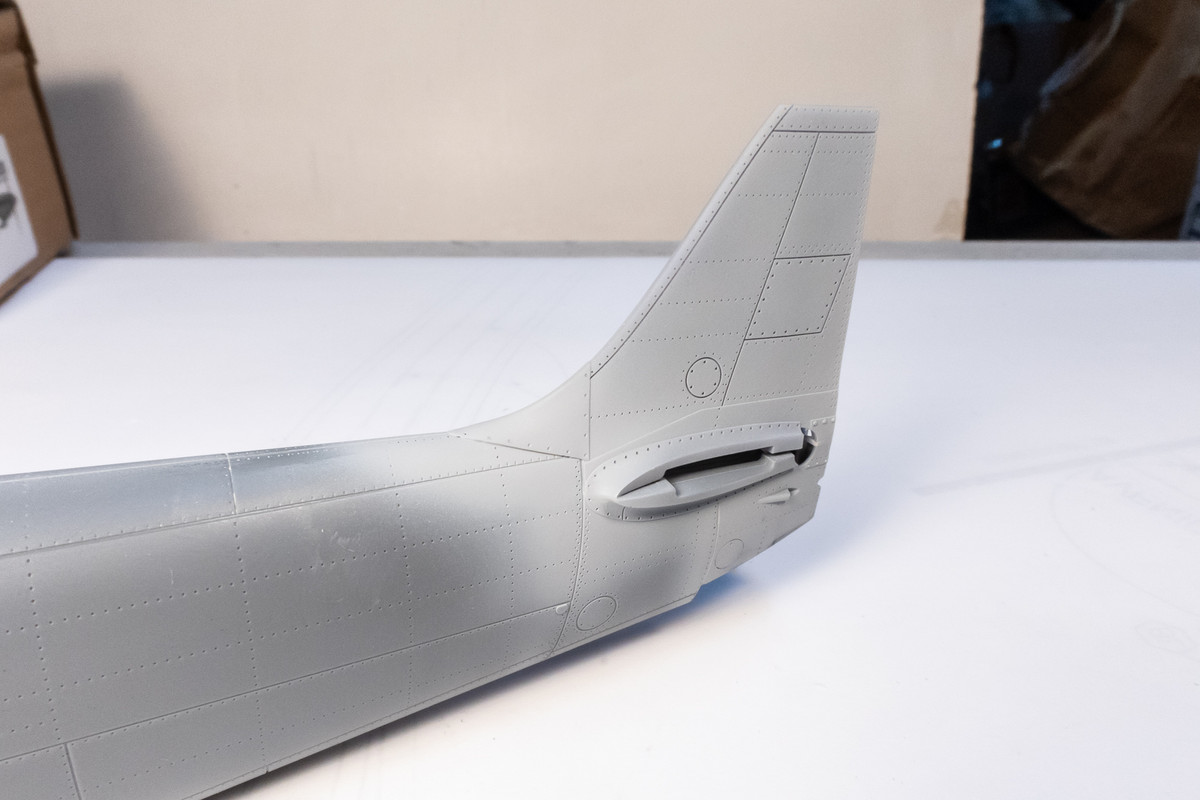
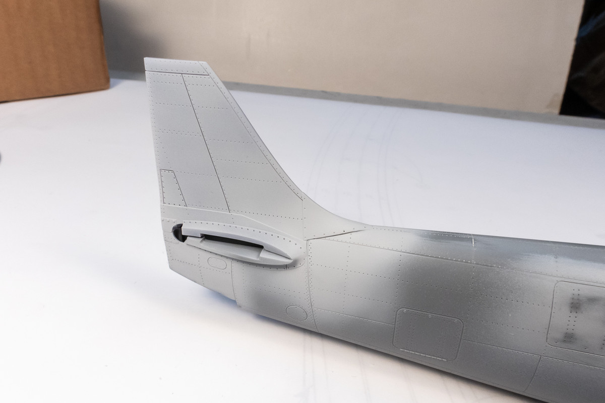
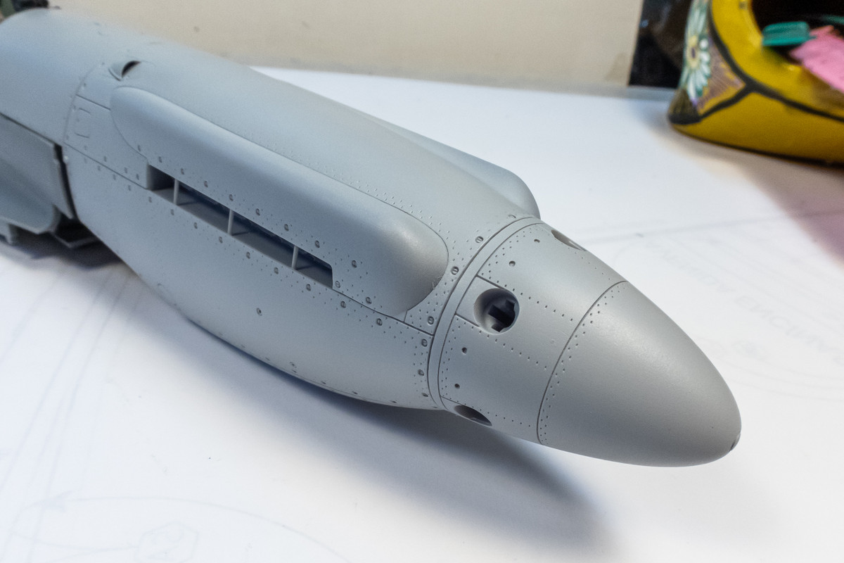
Continuing work on the XIVe conversion... the tail attachment is being slowly cleaned up. It's incremental work to try and get it as seamless as possible.
Image
Image

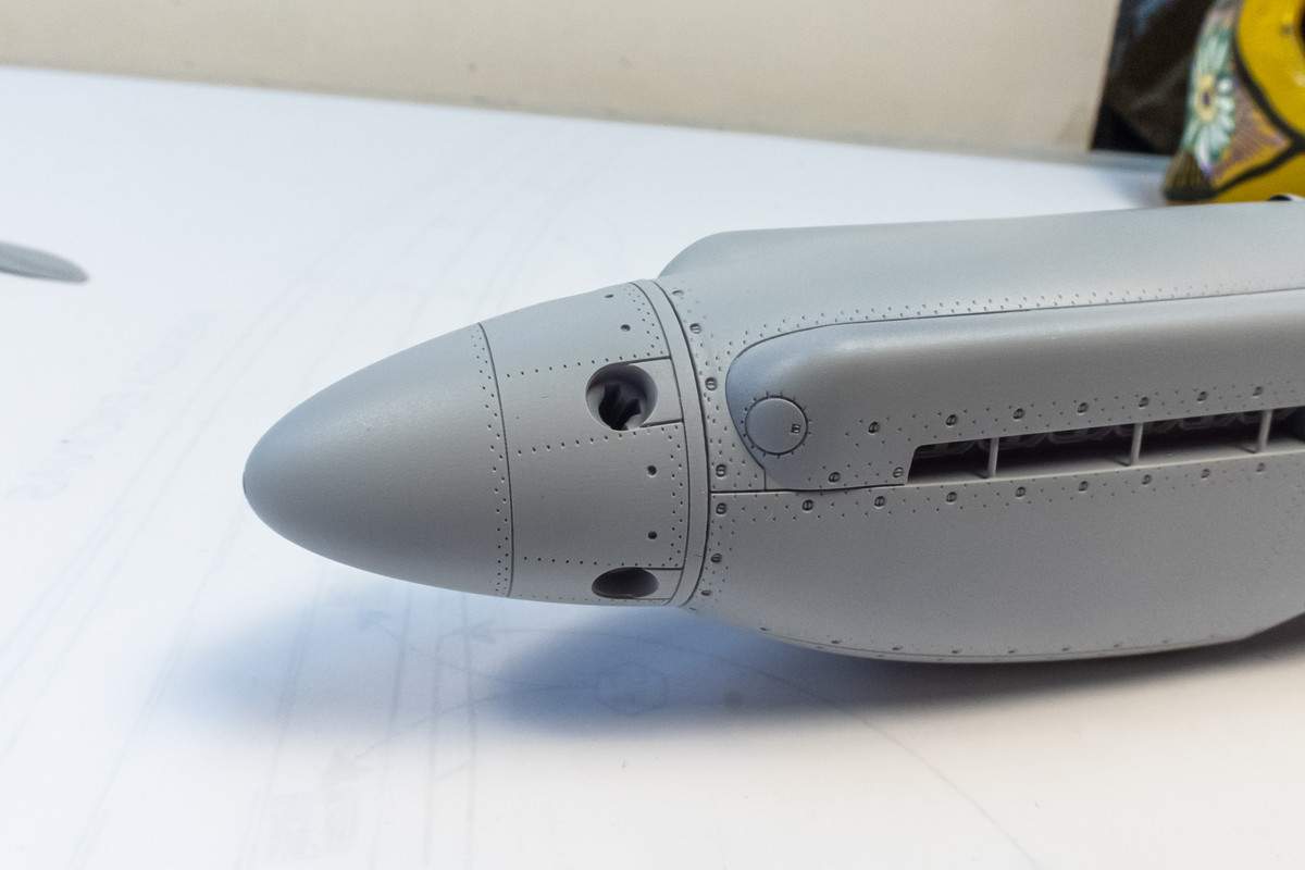
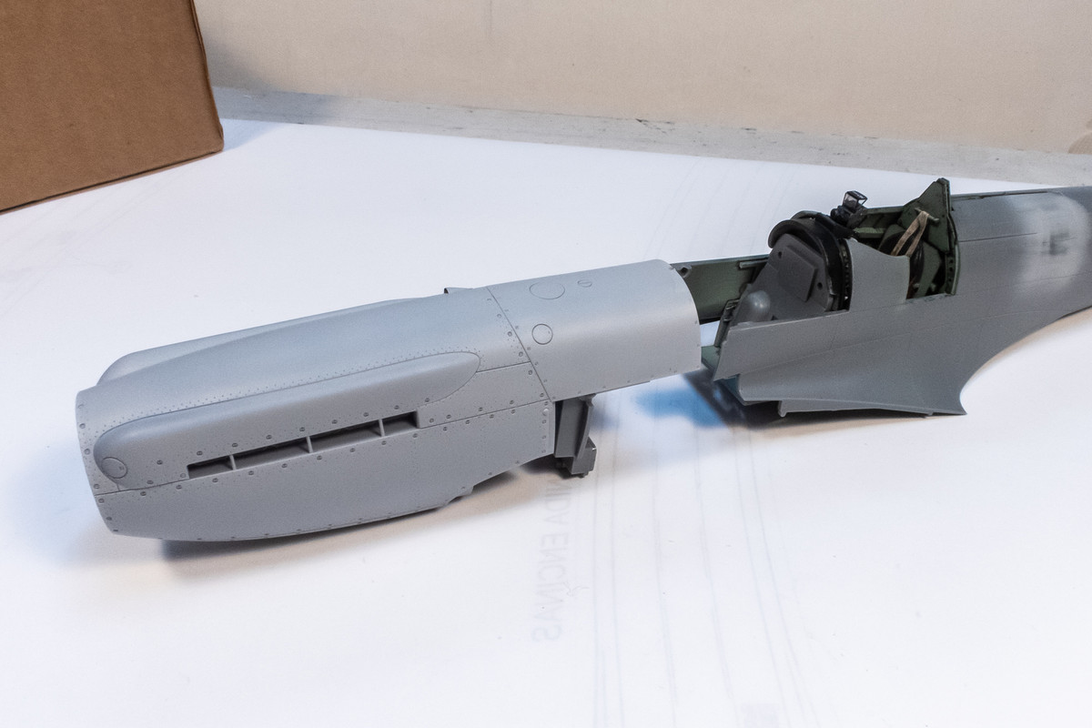
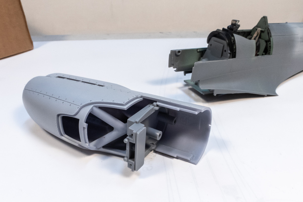
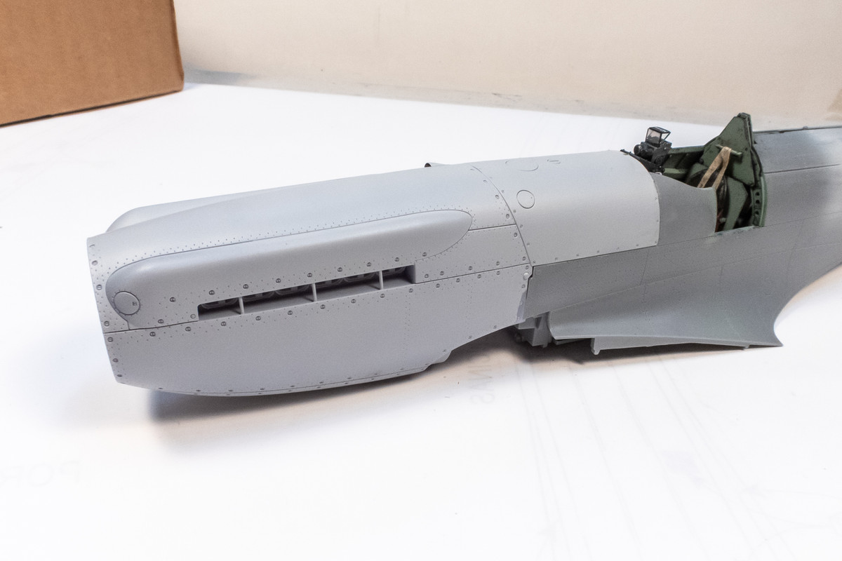
I figured that I can move forward with the attachment of the big Griffon-engine nose piece onto the fuselage. Preliminary fit checks have been very good so far.
Image

This insert was placed onto the two pins within the resin nose but not glued into place. A little wriggle room helps to get the nose into the correct position.
Image

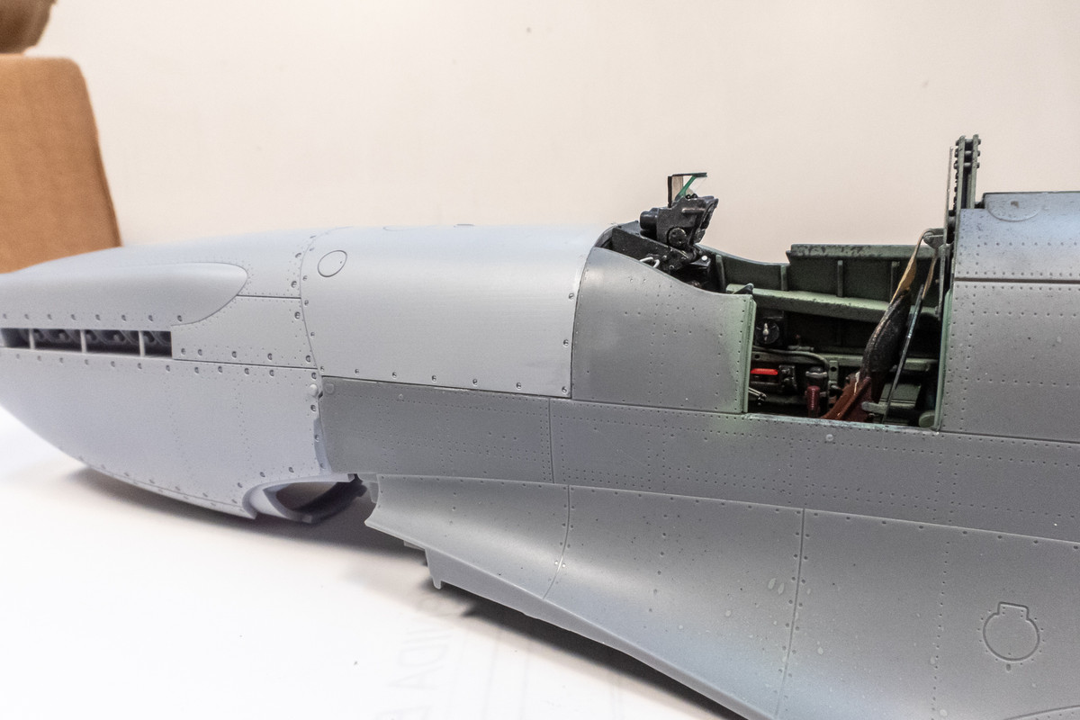
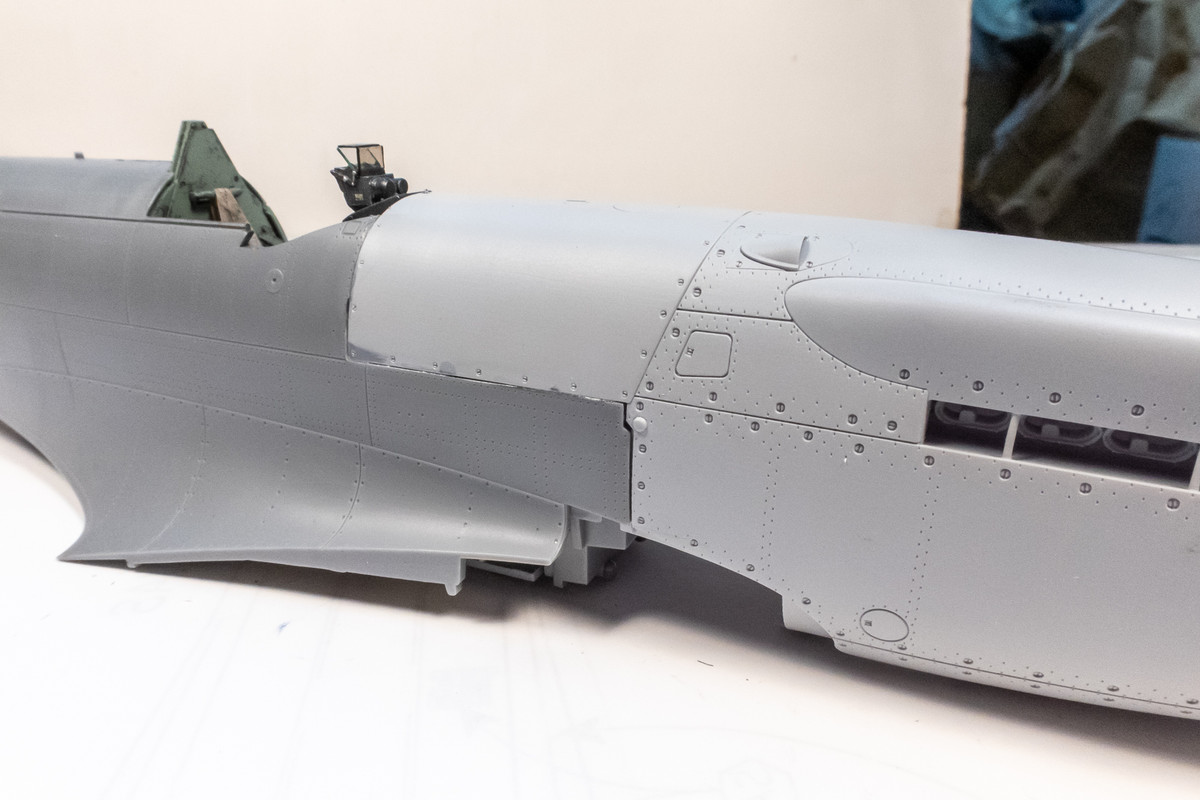
Once the nose is placed into position, making sure that the insert snaps into place, thin CA glue is seeped into the joints while holding the parts together. The port side fits as well I could have hoped. Clean up should be very simple on this side.
Image
Image

The starboard side is almost as good.
Image

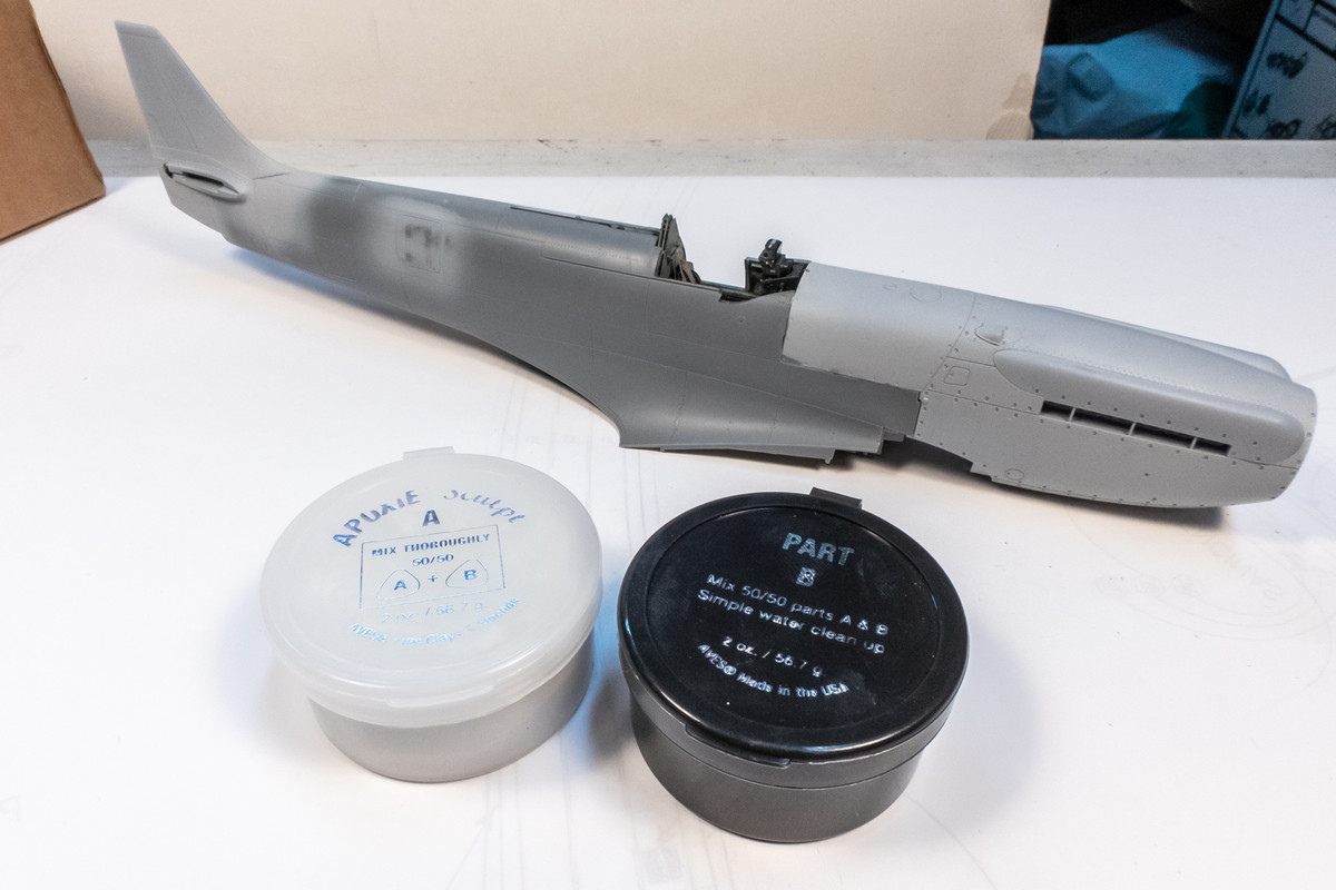
The first step of the joint work is to fill the obvious gaps with non-liquid putty. I've been using Apoxie Sculpt but Milliput works just as well.
Image

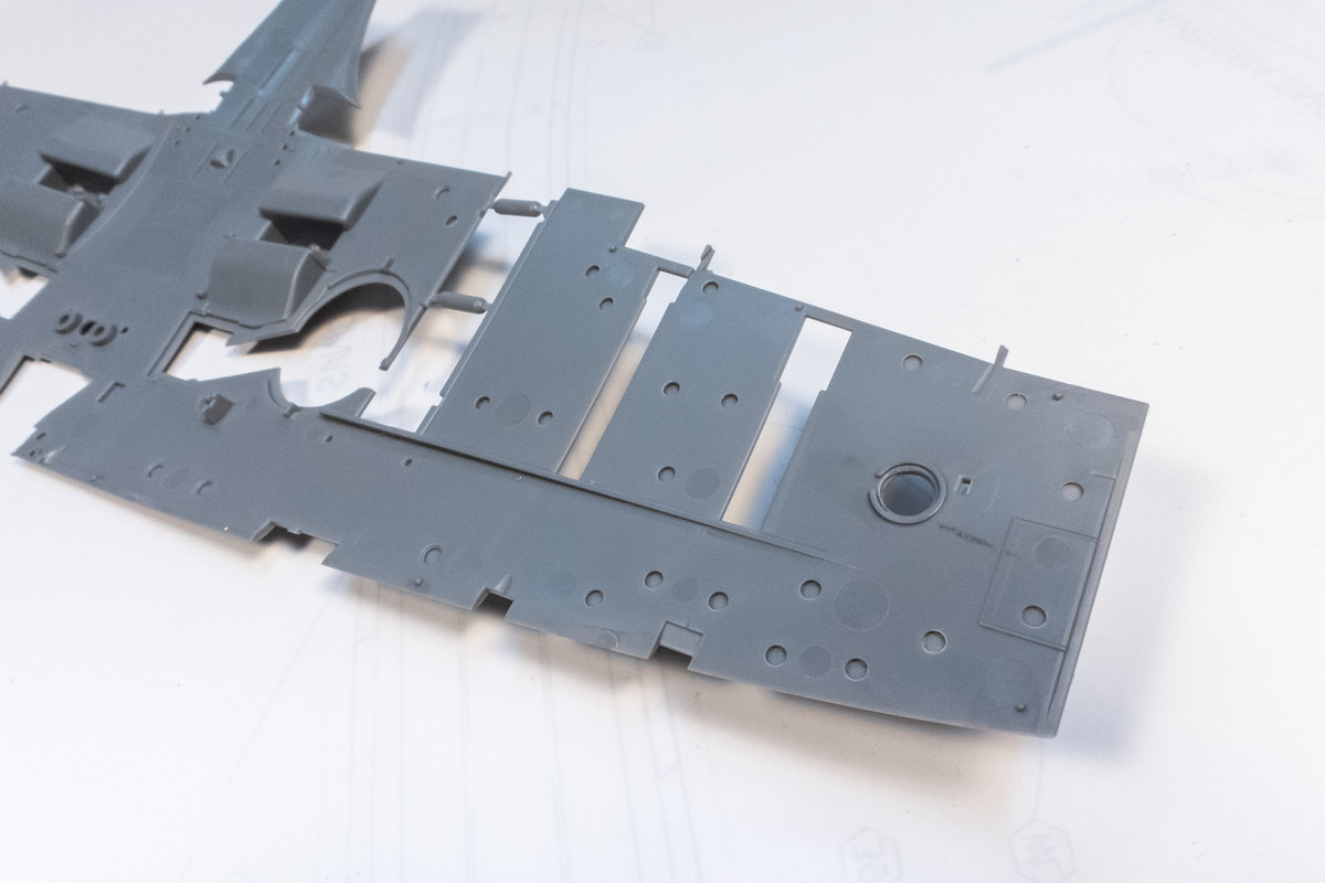
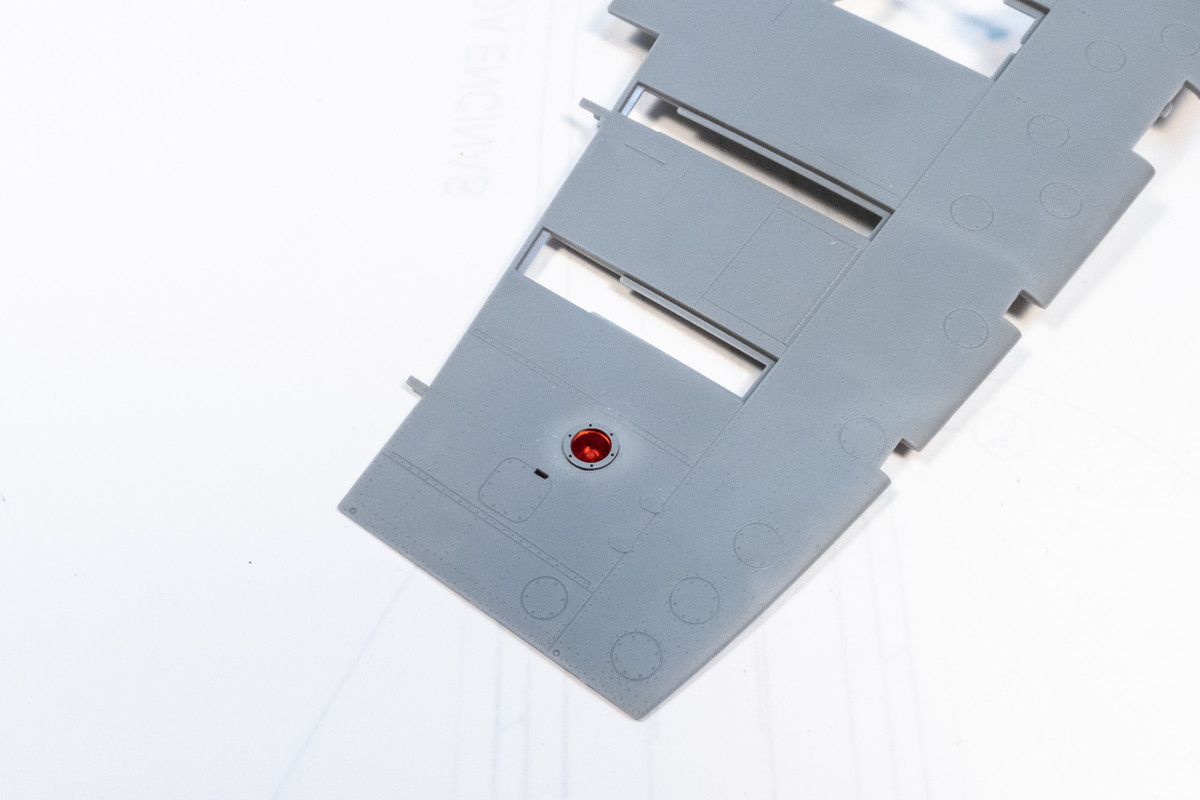
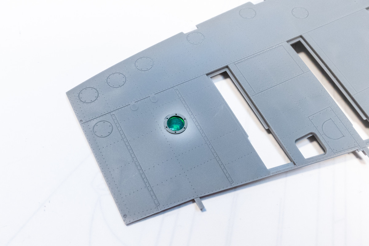
Jumping over to the wing bottoms, the wing light locations are drilled out.
Image

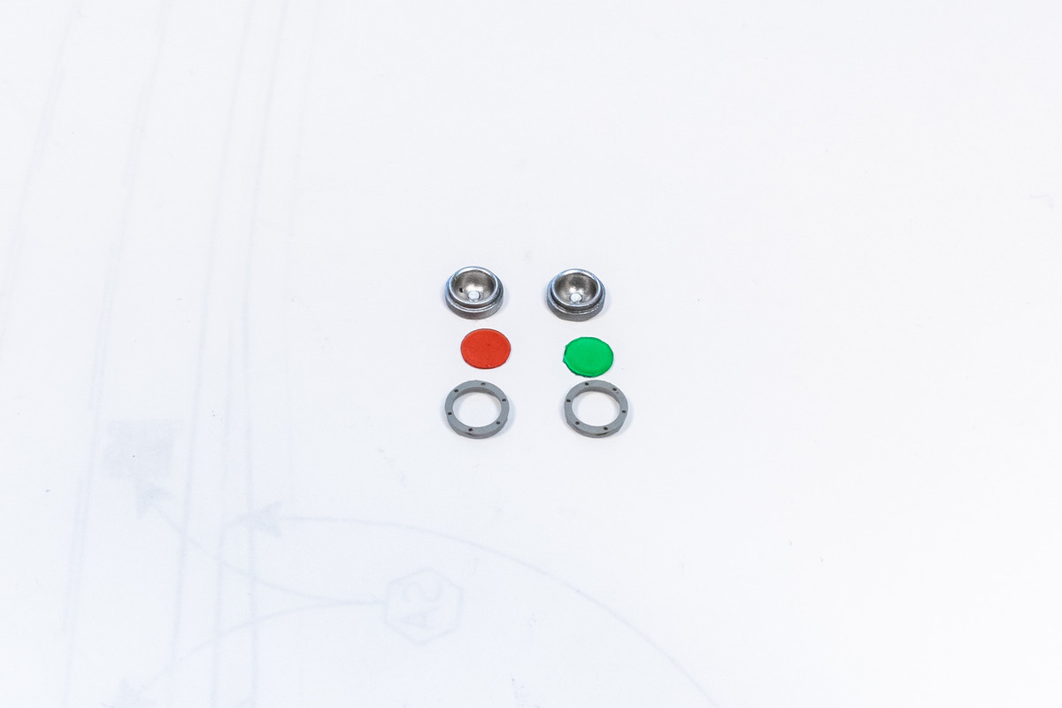
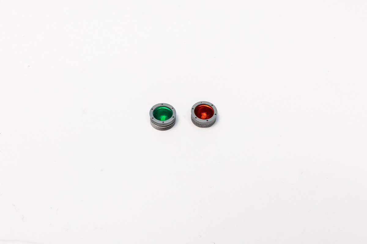
LFD provides very nice drop-in lights. All you need to add are the lenses, which have been punched from clear acetate and painted clear red and green. Make sure you measure the diameter of the lights BEFORE drilling your holes in the wing bottom. LFD has put a thin lip around the top of the light. You want your drilled hole to accept the body of the light but smaller than the lip so that you can simply drop in the lights from the outside. If you drill the hole too large, the whole light will drop through, making installation much more complicated.
Image
Image

Because of that little lip around the light bezel, I can leave off the light until all painting is done, which will avoid the need for any masking.
Image
Image
John aka JKim
-----------<><
Image
User avatar
jkim
Elite Member
Posts: 4073
Joined: Mon Apr 10, 2017 4:03 pm

Re: Tamiya 1/32 Spitfire XIVe Conversion

Post by jkim »

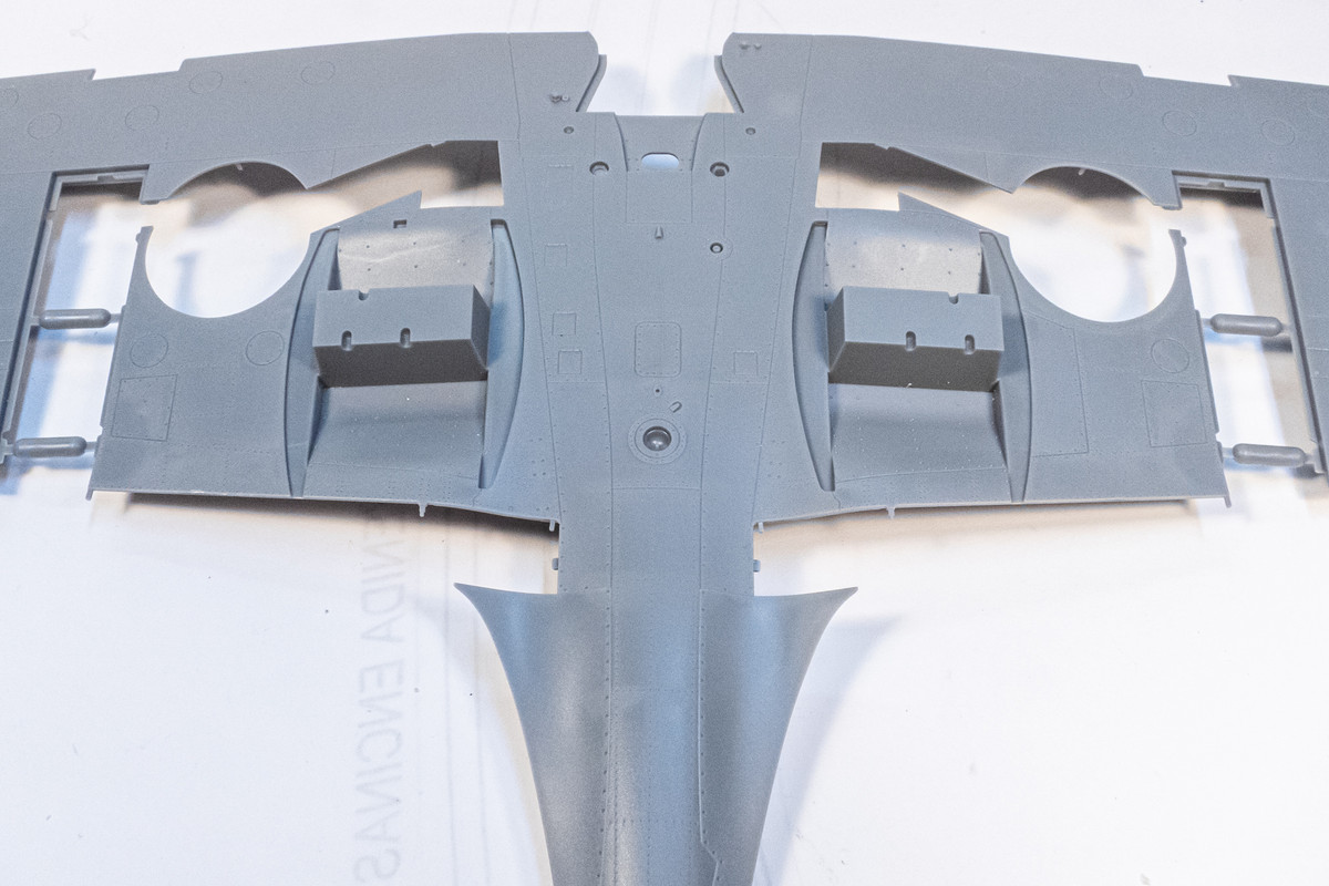
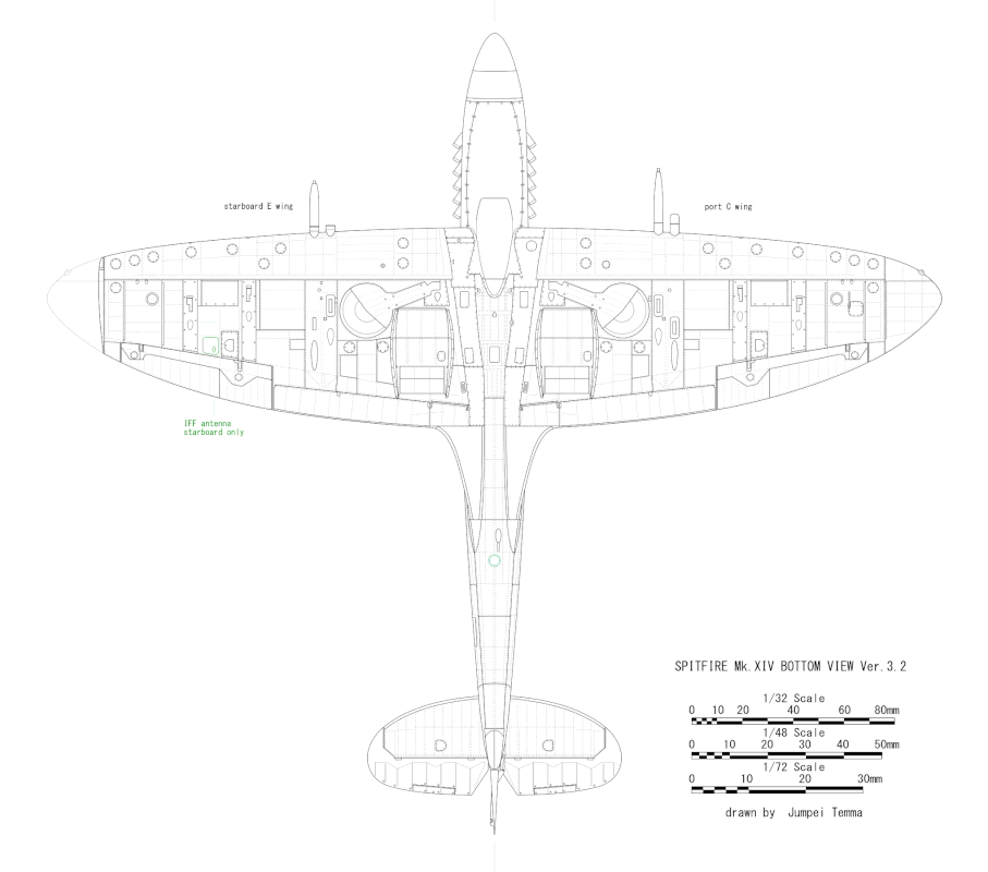
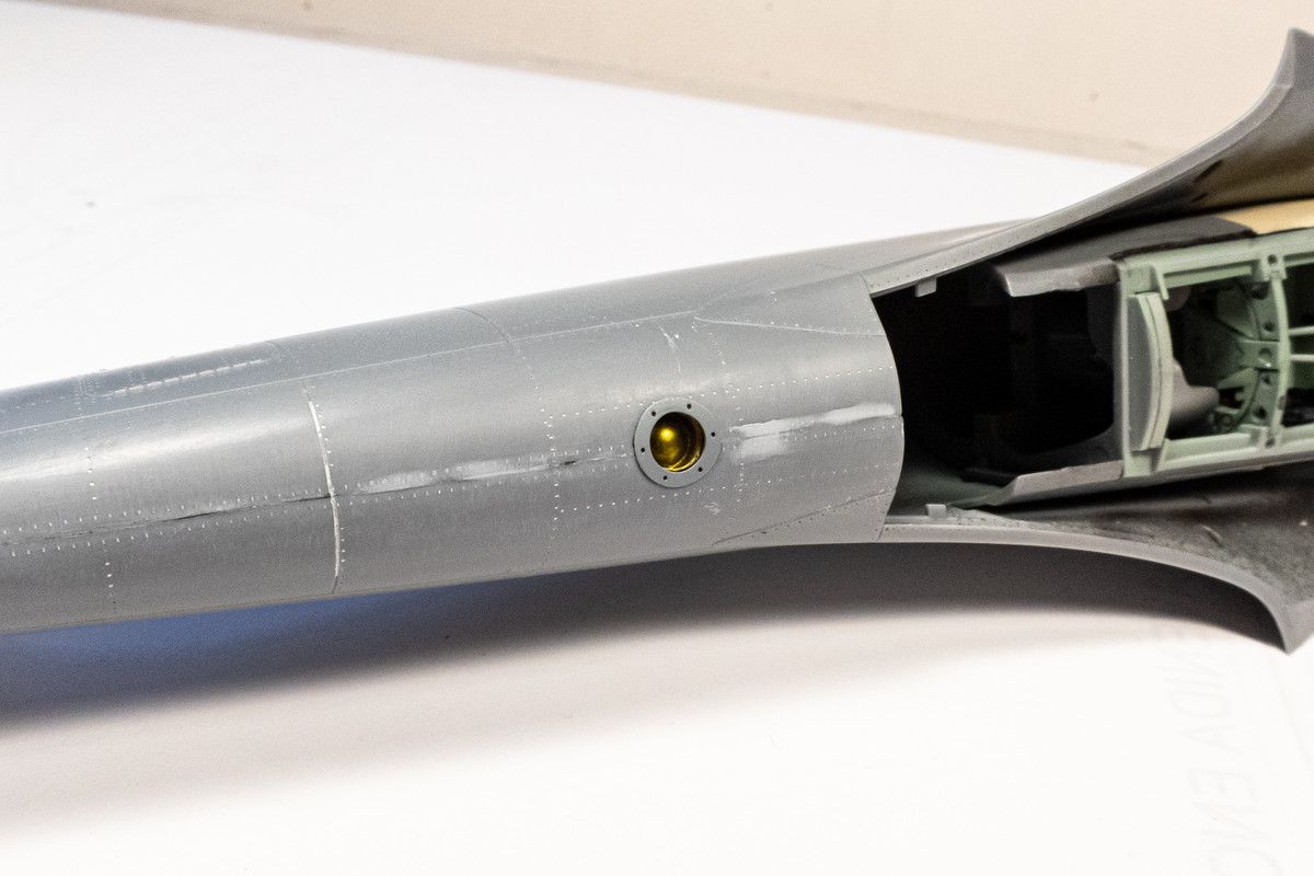
Based on my research, I believe that the central light located on the wing bottom between the two radiator boxes was not present on the XIVe.
Image

I believe this light was moved further aft, as shown on this drawing from modeler Jumpei Temma.
Image

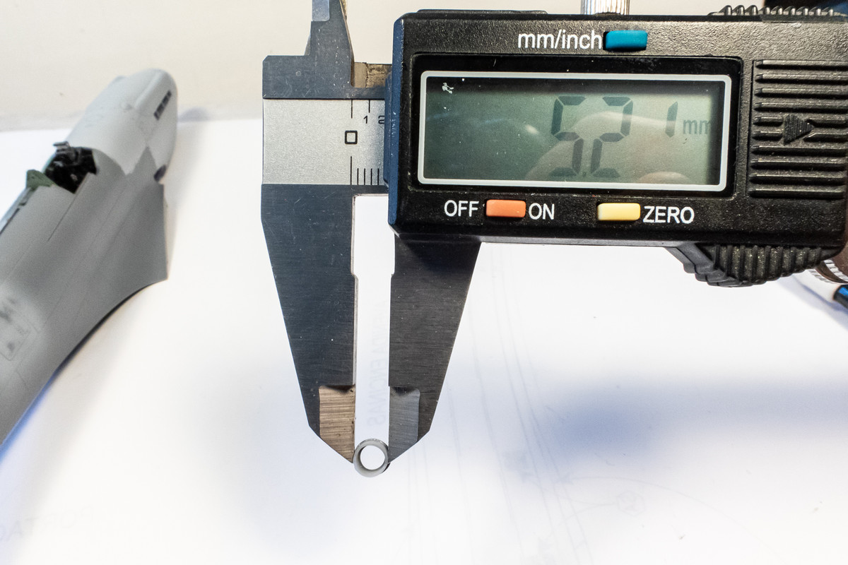
Similar to the wing lights, LFD provides a light for this fuselage position.
Image

First, I measured the body of the light... about 5.2 mm
Image

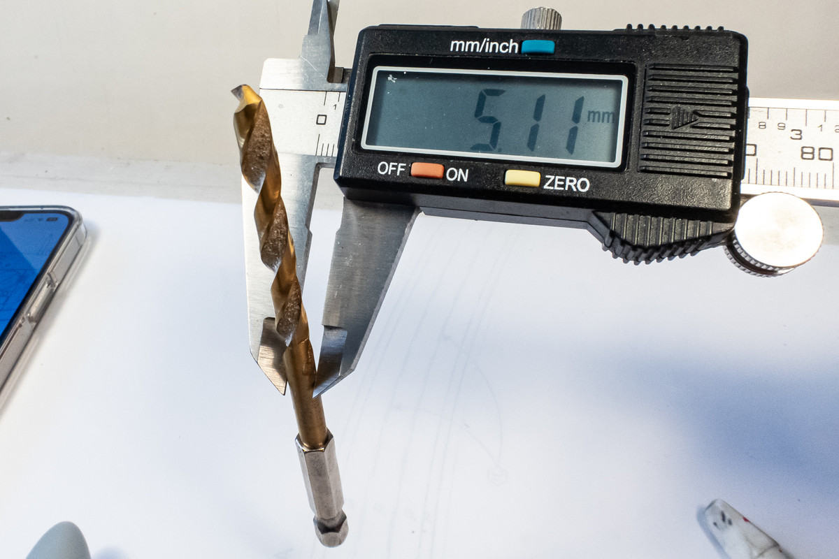
Next I find a drill bit that is slightly smaller than the light.
Image

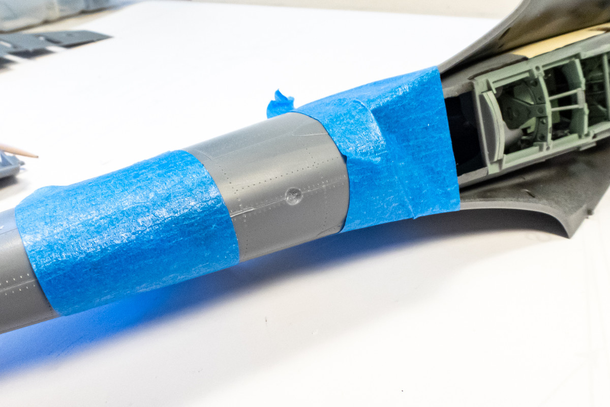
The location for the new light is marked on the fuselage and a pilot hole is created using a smaller bit size (2mm). The tape is a precaution to protect the surrounding area but more importantly, to hold the fuselage halves together. Drilling a hole this size will create a lot of stress on the joint and the last thing I want is for the fuselage parts to separate during drilling.
Image

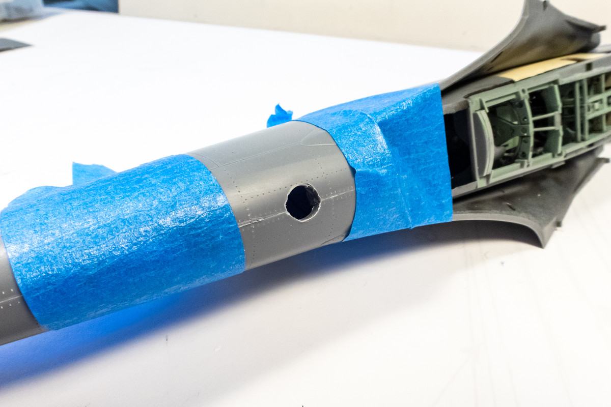
As carefully and as accurately as I could manage, the hole is drilled using my old Makita hand drill. Thank goodness for the tape because I heard a loud crack as I was drilling... the glue joint had become undone.
Image

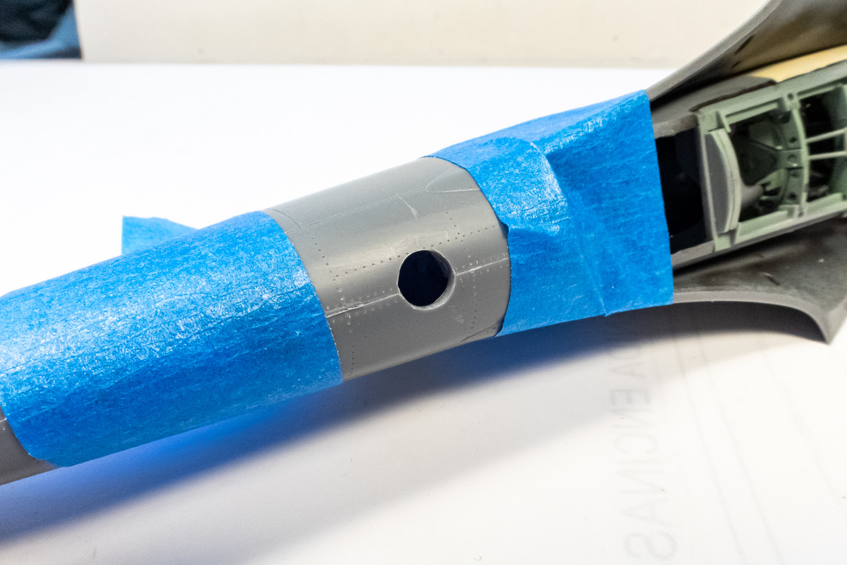
The hole is a little smaller than the light body so it needs to be slowly enlarged.
Image

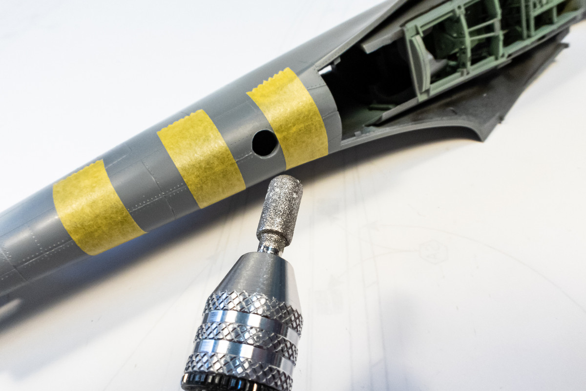
I found this cylindrical grinding bit that was exactly 5mm in diameter and it was the perfect tool to enlarge the hole.
Image

Big sigh of relief as this light position has been established without any issues. You can see the remnants of my putty work as a result of re-doing the popped glue seam.
Image
John aka JKim
-----------<><
Image
Post Reply

Return to “Aircraft Work in Progress”